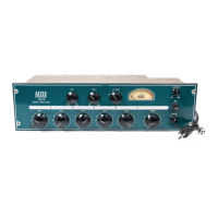
DESCRIPTION
The AL TEC 1593B Power Amplifier deliv ers up to 50
watts of output power for all types of sound reinfor cement
systems. It remain s stable with operating conditions of
varying line voltages and with all types of loads, including
long, unloaded speaker lines having considerabl e capacitance.
Performance character istics are shown in Figur es 1 and 2.
A switchab le, two-section highpass filter is provi ded to pro-
tect driver loudspeakers fro m excessive low-frequ ency power
demands.
AL TEC's Active Dissipatio n Sensing Circuit prov ides fail-
safe protection for the out put transistors. Circui t action is
immediate and effec t ive at all frequencies within the pass-
band of the amplifier, limiting only that portion of program
material that would damage or degrade the output
transistors .
ACCESSORIES
A plug-in 15095A or 15335A Line Transforme r is available
to provide line isolation. Input sensitivity for full-rated
amplifier output is 0.2V rms with the 15095A Transformer
and 0.8V rms with the 15335A Transformer.
The 42526 Shelf Mount Cover is available to enclose the
1593B for shelf use. It tilt s the 1593B for easy access to
front panel controls. The sides and top extend beyond the
front panel to prevent accidental changes of control settings.
The cover provides easier handling for portability and it is
sturdy enough to support lightw eight equipment placed on
top of it. Four polyethylene feet prevent marring of sur-
faces. The AL TEC green finish matches the front panel of
the 1593B.
INSTALLATION
The 1593B may be installed in a standard 19-inch equip -
ment rack, or in the 42526 Shelf Moun t Cover accessory
for shelf use. Vertical space required is 5¼ inches (3 rack
units).
RACK INSTALLATION
Step 1.
Step 2.
Step 3.
Remove four screws securing fr ont panel. Open
and lower panel as shown in Figure 3.
lnstal I 1593B in equipment rack w ith appro-
priate four screws supplied .
Close front panel and secure with four screws
previously removed.
SHELF INSTALLATION
The 1593B may be shelf mounted as desired after installing
the AL TEC 42526 Shelf Mount Cover (refer to 42526
Installation Instructions).
VENTILATIO N
The 1593B generates minimal heat during normal use. Al-
though the amount of heat is relatively low, the amplif ier
'Q ' BALANCE { Rl40
CONTROLS Rl4l
POWER DRIVER
PCB ASSEMBLY
POWER DR IVER
PRIMARY POWER
TERMINAL BOARD(TB3)
BALANCE CONTROL(Rll6)
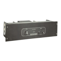
Figure 3. Front View With Hinged Panel Open
- 4-