12 | 18
5 Starting up
If an adjustment (A-K-1K / A-D-1K) has been ordered in combination with the amplifier(-s) and/or
transducers(-s) it may be necessary for a slight fine adjustment nonetheless. This is due to possible
various environmental influences as well as to mounting etc.
If any visual damage or malfunctions are noticed, the measuring system must be switched off and
marked appropriately.
■
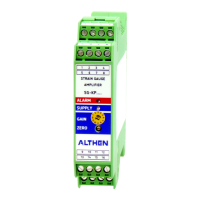
Mounting transducer and amplifier
■
Connect transducer to the amplifier
■
Connect multimeter to analogue output
■
Connect supply voltage – consider pin assignment
■
Allow the system about 30 min. to warm up
■
Check function and calibration of the system
Notice: The allocation of transducer / amplifier is to be complied with. After replacing a transducer,
the calibration has to be checked. It is to be noted that there is a slight dependence between zero-
point adjustment and amplification (gain).
5.1 Zero point adjustment range
It is to be noted that there is a slight dependence between zero-point adjustment and amplification
(gain).
The zero-point adjustment range is approx. ± 10 %.
This range can be changed by setting the dip-switch according to the table below:
Setting the zero point:
Increase DIP60/2 DIP60/1
+5 V
OFF ON
-5 V
ON OFF
Notice: A base load reduces the remaining load capacity by just that value. Overloading may cause
damage!
Base load / tare + maximum load to measure = capacity of transducer
DIP50-1 DIP50-2 DIP50-3 DIP50-4 corresponding to the analogue voltage output
ON ON ON ON -1,0 V … +1,0 V
ON OFF OFF ON -3,3 V … +3,3 V
ON OFF ON OFF +0,4 V … +4,0 V
OFF ON OFF ON -4,0 V … -0,4 V
 Loading...