PCB test procedure (MAC2.2/2.3)
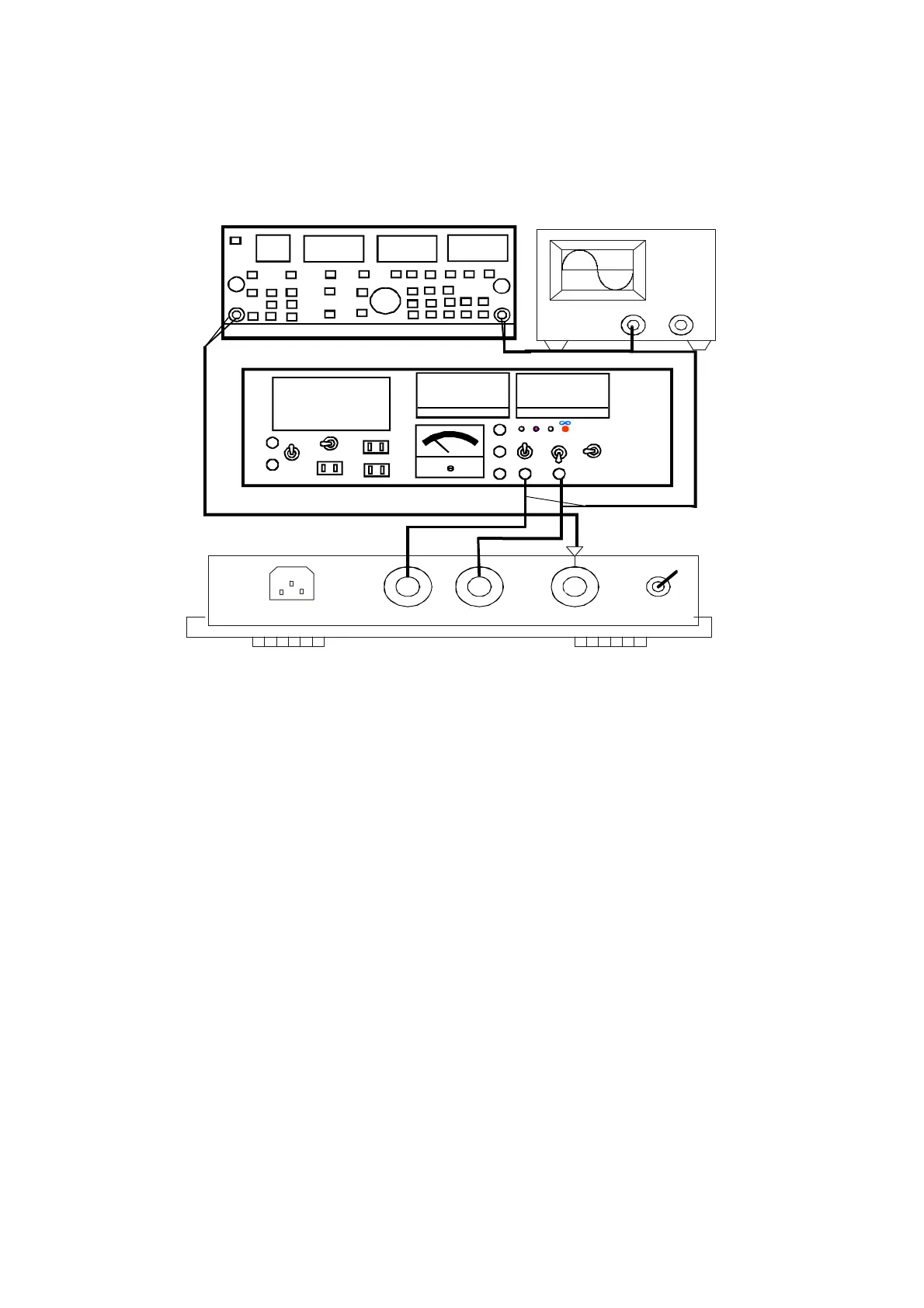
Wiring Diagram
7.2. PCB test procedure & specification
instrument: (1) audio analysis 7724 (2) oscillograph (3) two loads 4Ω (4) power source (5) DMM.
7.2.1: Without the signal input, adjust VR1, to make DC voltage of R11(3000-R PCB) and R13 (3000-L PCB) by
0.16 ±0.01V(MAC2.2/2.3).
7.2.2: Input sine wave 1KHz 3dB to CH-A and CH-B, the output of each channel should be 36V larger(MAC2.2) 42V larger
(MAC2.3), distortion less than 0.1%.
7.2.3: Input sine wave 1KHz 3dB, and then connect separately with 2Ωload. Adjust R2 & R3(PSA-3000-R) /R2
&R3(PSA-3000-L) to make the output 29.2 ±0 .2V(MAC2.2), 37.5 ±0.2V(MAC2.3).
7.2.4: After heating P.T.C. on the heat sink for 10 seconds, the fan should work quicker. Heat P.T.C. about 5 seconds more
again, then the signal should be cut off automatically. (CHA, CHB)
7.2.5: Set the switch to PARALLEL, input signals from CHA, output should be from CHB .
2.6: Set the switch to BRIDGE. Input signals from CHA. BRIDGE output should be more than 68V(MAC2.2 8Ω)/84V
(MAC2.3 8Ω).
7.2.7: Turn on the filter, then input 30Hz sine wave , output should attenuate 8.5±1dB(CHA, CHB)
7.2.8: Turn on the LIMIT, increase input signal to +6dB gradually, output distortion should be limited less than 2%. (CHA, CHB)
7.2.9 Set the volume to minimum. Make the output terminal short-circuit. When set the volume to maximum, the power
consumption should be less than 400W.(CHA, CHB)
Note: When PSA-3000-R is tested, do all the items above. When PSA-3000-L is tested, it is unnecessary to do item 5.
OSCILLATION
OUTPUT INPUT
POWER
CH1 CH2
VP-7724A
POWER
88
8888
8
888
8
88 8
8888
V
8888
A
110
NORL
SHORT
220
NORL
110V
220V
LOADSEL.
LOADOUT
LOAD
S.P.
AC
UNSWITCH
DCIN
DCOUT
+
+
_
ADR-245
-
+
4
8
16
ACINPUT
AudioAnalyzer
2/4/8Ω