B
Barry WatsonJul 27, 2025
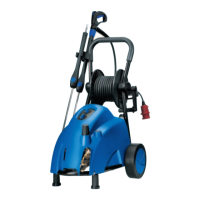
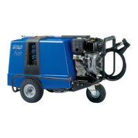
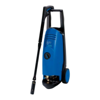
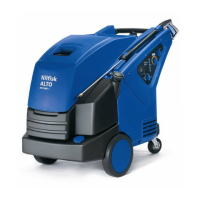
What to do if the motor stops on my Alto Poseidon 7 Pressure Washer?
- AAdrienne BallJul 27, 2025
If the motor of your Alto Pressure Washer stops, you should check several components. Examine the circuit breakers, contactor and coil, electrical connections and plug, and the temperature sensor in the motor. Also, check the start switch, print and reed switch, and finally, inspect the piston for the bypass valve.