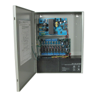
- 2 - Sub-Assembly
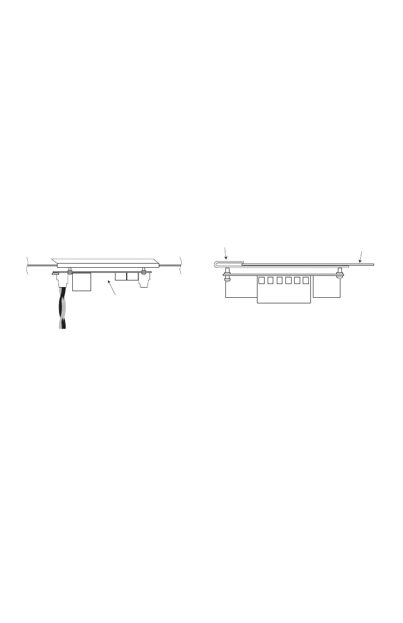
Top edge of Enclosure
LINQ2 bracket
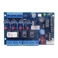
LINQ2 Module
eFlow Power
Supply/Charger
Fig. 1
Overview:
Altronix manufactures a wide variety of sub-assemblies suitable for many tasks in fire alarm, access control,
network communications, surveillance, and other security applications.
Installation Instructions:
Wiring methods shall be in accordance with the National Electrical Code/NFPA 70/NFPA 72/ANSI, and
with all local codes and authorities having jurisdiction. Product is intended for indoor use only and should be
installed by qualified personnel.
Refer to individual Sub-Assembly Installation Guides for mounting and connecting specific boards.
Installing LINQ2 Board:
1. Using the mounting bracket mount the LINQ2 network module to the desired location on the enclosure.
Secure the module by tightening the longer screw on the front edge of the mounting bracket (Fig. 1, pg. 2).
2. Connect one end of the supplied interface cable(s) to the ports marked [Power Supply 1] and
[Power Supply 2] on LINQ2 (Fig. 1, pg. 2). When connecting to one power supply use the connector
marked [Power Supply 1].
3. Connect the other end of the interface cable to the interface port of each eFlow power supply board.
4. Connect Ethernet cable (CAT5e or higher) to the RJ45 jack on the LINQ2 network module.
For access control and fire alarm signalling applications the cable connection has to terminate is the same room.
Refer to the LINQ2 Installation Manual.