Power Supply Specifications:
AC Input: 115VAC / 3.2 amp @ 60Hz
Output: 12VDC - 24VDC. Maximum 2.0 amp per output.
T
otal of 6.5 amp in Alarm Condition.
Battery: For 12VDC operation use a 12VDC / 12AH battery
F
or 24VDC operation use two (2) 12VDC / 12AH batteries connected in series
Stand-by Current: 75mA
EOL Resistor: 2.2K (2200 ohm)
(end of line)
Stand-by Specifications:
Stand-by Batteries Stand-by Time Alarm Output Aux Output
Total Amp/Minutes Current
24VDC/12AH 24 Hours 6.5 Amp/15 Minutes 50mA
(use tw
o (2) 12VDC batteries in series) 60 Hours 6.5 Amp/5 Minutes -
12VDC/12AH 24 Hours 6.5 Amp/15 Minutes 50mA
60 Hours 6.5 Amp/5 Minutes -
24VDC/7AH 24 Hours 6.5 Amp/5 Minutes -
Installation Instructions:
The AL600ULADA should be installed in accordance with article 760 of The National Electrical Code as well as
NFPA 72 and all applicable Local Codes.
1. Mount the AL600ULADA in a desired location. It is recommended to first review the following tables for screw
terminals, switch selection and LED status indications. This will greatly facilitate installation hook-up.
Carefully r
eview:
Power Supply Specifications (pg. 3)
Stand-by Specifications (pg. 3)
Input / Output Selection Table (pg. 4)
LED Status Indication Table (pg. 4)
Terminal Identification Table (pg. 5)
Typical Application Diagrams (pg. 6)
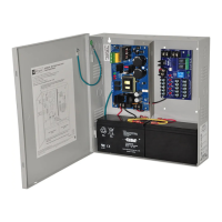
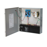
2. Connect the black and white transformer leads of AL600ULADA to a separate
unswitched AC circuit (115V
AC, 60Hz) dedicated to the
Fire Alarm System (Fig. 1, pg
. 3). Connect green lead to earth ground.
Keep power limited wiring separate from non-power limited wiring
(115V
AC / 60Hz Input, Battery Wires). Minimum .25” spacing must be provided.
3. Set switch SW1 on Power Supply Board for desired output voltage. Open for 24VDC
(f
actory set), Close for 12VDC.
4. Measure output voltage before connecting devices. This helps avoid potential damage.
5. Connect battery to terminals marked [+ BAT --] on the Power Supply Board
(battery leads included). Use two (2) 12VDC batteries connected in series for 24VDC operation.
6. Set output selection switches marked (OUT1 through OUT4) to follow corresponding input (IN1 & IN2)
(Input/Output Selection T
able pg. 4).
7. Connect FACP output to desired AL600LGK logic board inputs and notification appliances to desired AL600LGK
lo
gic board outputs (Typical Application Diagrams pg. 6).
8.
For connection of smoke detectors, digital dialer (Optional Hookup Diagram pg. 7).
9. To disable ground fault detection install insulating washer between the board and standoff (Fig. 4B/4C, pg. 7).
General Information:
• For all Class B hookups SW1 & SW2 on the AL600LGK logic board must be open.
For all Class A hookups SW1 & SW2 on the AL600LGK logic board must be closed.
AC
AL601ULB
AC AC
+
BAT ---
OPEN = 24V SW1 CLOSED = 12V
DC
RL2
RL3
RLY1
POWER SUPPLY
ALTRONIX CORP.
PTC2
AC TROUBLE
DELAY OPTION
J2
IC3
IC2
AC FAIL
NC C NO
BAT FAIL
NC C NO
XFMR
Green
Lead
(ground)
AL600LGK
ALTRONIX CORP.
BKLYN, NY 11220
SW1
--
DC
+
SW2
+ OUT1 --- + OUT2 --- + OUT3 --- + OUT4 ---
OUT1
OUT2 OUT3 OUT4
INP1 INP2
FAULT
--- AUX +
NO REMOTE C
NC C NO C "FAULT" NC
AUX
RESET
OUT1 OUT3
CLOSED - INP1
OPEN - INP2
OUT2 OUT4
CLOSED - INP1
OPEN - INP2
LOWER TERMINALS
IN1+
UPPER TERMINALS
Black
Lead
White
Lead
115 VAC input
60 Hz,
3.2 amp
+
DC
--
IN1--
IN2+
IN2--
RET1+
RET1--
RET2+
RET2--
Fig. 1
- 3 -