Addendum
Ad-2
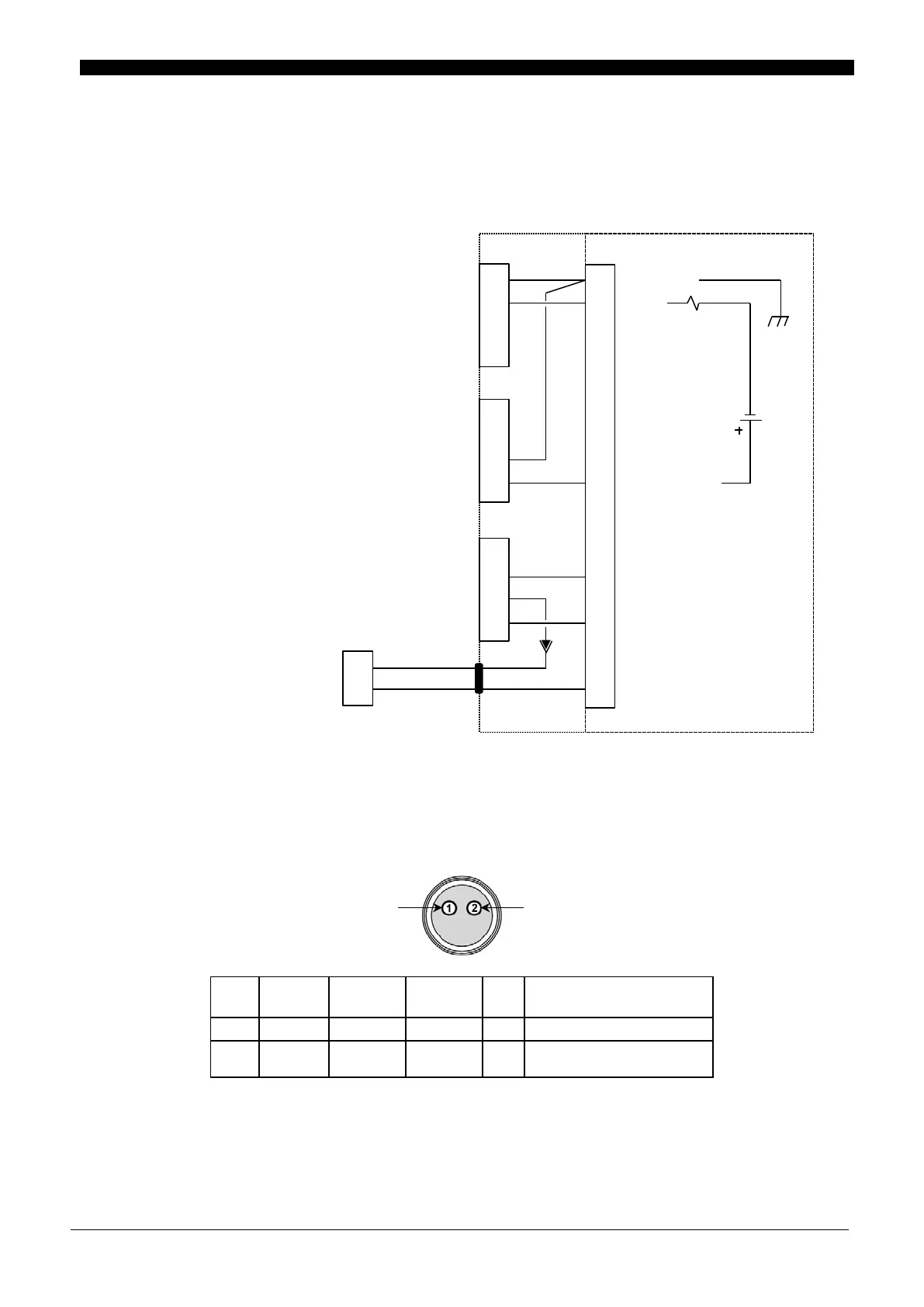
-MU – I/O Accessory Box Schematic + Mating Connectors
The terminal strip shown in the schematic below is located behind the –MU –I/O Accessory Box. Refer
to Chapter 8. External Interface for more information on the available signals on this terminal strip.
PANEL CONNECTOR DETAIL
Firing Switch Cable
PIN #
SIGNAL
NAME
MAX
VOLTAGE
MAX
CURRENT
I/O COMMENTS
1 2ND
24 VDC
5 mA I Same as Terminal Block # 5
2 24V- --- --- ---
Connects to Footswitch
Connector
1
2
3
4
1
2
3
4
1
2
3
4
34
32
31
4
6
5
2
1
SOL COM
SOL1
SOL POWER
1ST
COM
2ND
Terminal Strip
Mating Connector: AWT # 520-107
Backshell: AWT # 245-084
Terminals: AWT # 253-001
Mating Connector: AWT # 520-154
Backshell: AWT # 245-084
Terminals: AWT # 253-002
FTSW: FOOTSWITCH INPUT
Mating Connector: AWT # 520-009
FIRING SWITCH INPUT
Mating Connector: AWT # 520-011
 Loading...


