IPB-5000B
5. Installation and Connection
5-2
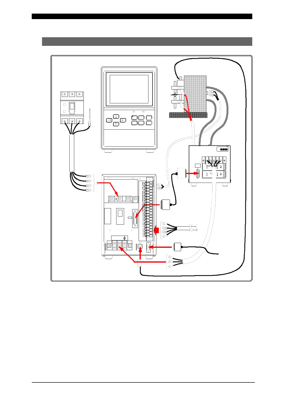
(2) Connection
Numerals of (1) to (8) in the above figure represent the order of connection
procedures in the following pages.
* 1: All items are separately sold except IPB-5000B.
* 2: The Voltage Detecting Cable is used only for Constant Voltage Control,
Constant Current/Constant Voltage Combination Control and Constant Power
Control.
* 3: Communication Cable is used only for connecting Personal Computer (PC).
* 4: Displacement Sensor is used only for the model equipped with the Sensor.
To Ground (G)
Earth
Leakage
Breaker(40A)
Input
Cable
Welding Head
IPB-5000B
POWERSTART
CU RSO R
WE LD MEN U RE SET
EN TER
+-
11 37353331292725232119171513975
383634323028262422201816141210864
STOP
1ST
2ND
COM
SCH1
SCH4
SCH8
SCH16
SCH32
SCH2
SCH64
INT.24V
EXT.COM
WELDON/OFF
ERRORRESET
COM
COM
GOOD
NG
END
CAUTION
COUNTUP
READY
OUTCOM
OUTCOM
SOL1
SOL2
SOLCOM
PRGPROTECT
39
PARITY
(WE1STOP)
COM
W.INTERRUPT
P-00281-001
COUNTRESET
C ONT ROL SI G
2
31
(OPTION1)
(OPTION2)
SOLPOWER
(OPTION4)
(OPTION 5)
(OPTION3)
POWER OUT
P-1463
VU
I/O
SENS
SERIAL
NO.
JAPAN
MIYACHI TECHNOS CORP.
MADE
IN
A1
12 34
インバータ出力電圧300V時
FORINVERTEROUTPUT300V
インバータ出力電圧600V時
FORINVE RTEROUTPUT600V
POWER SUPPLY VOLTAG EPOWER SUPPLY VOLTAGE
AC380V~AC480VAC200V~AC240V
L1 L2 L3 PE
Front Panel
Rear Panel
Voltage
Detecting
Cable
*2
Secondary
Cable
Welding
Transformer
Input Terminal Block
Output
Cable
(Refer to Caution
at next page.)
[SENS] Cable
External I/O
Signal Cable
Match the designaton
of cable with terminal
for connection
*1
Start
Cable
(1)
(6)
(5)
(4)
(3)
(2)
(7)
(8)
Communication
Cable *3
Displacement
Sensor *4
To PC