IPB-5000B
6. Description of Display Screens
6-8
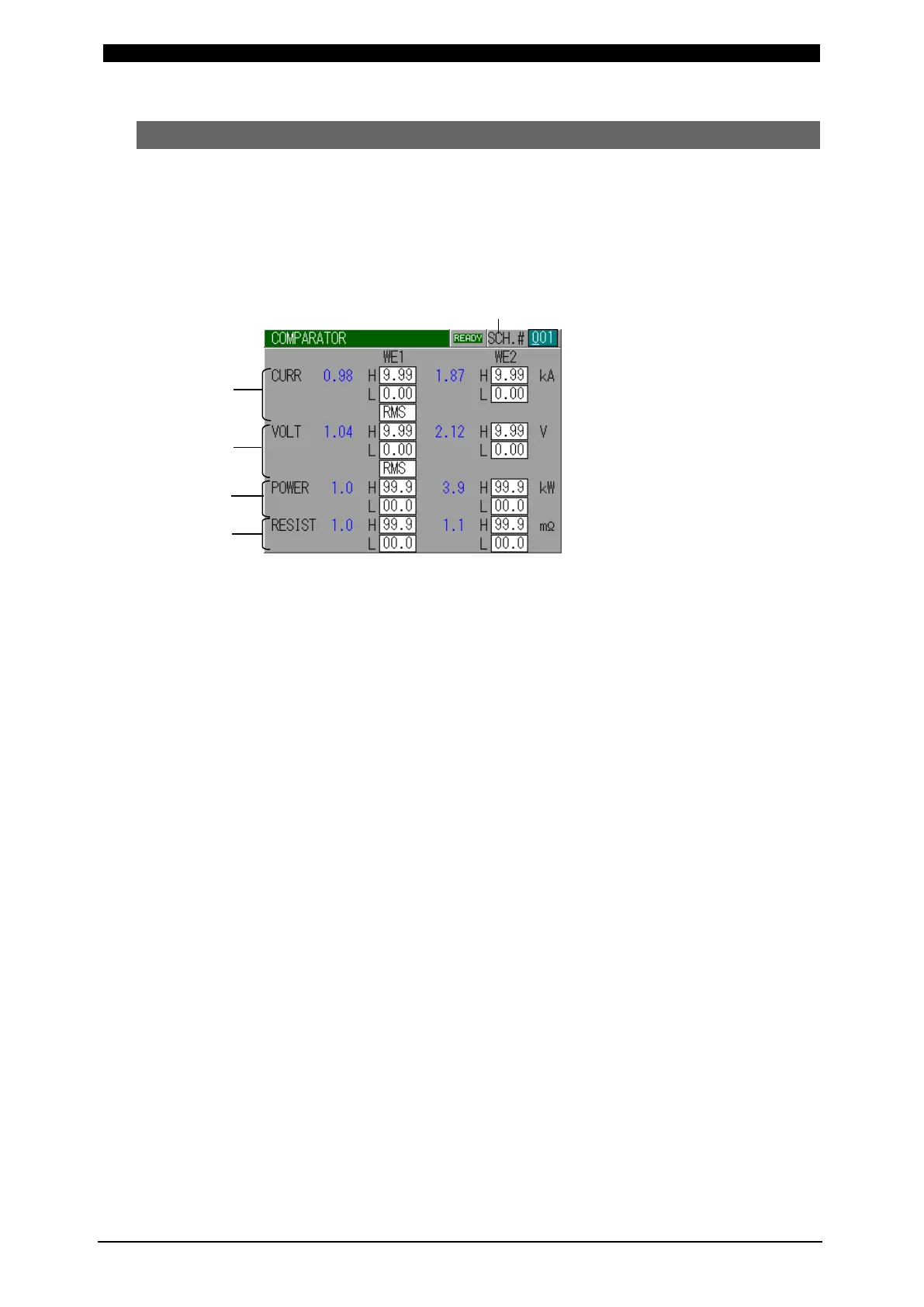
(5) COMPARATOR Screen
Set the upper and lower criterion of Current, Voltage, Power and Resistance for
judging “Good” or “No Good” weld. If the monitored value is inside the criterion,
Good is determined. If it is outside, No Good is determined.
If the monitored value equals to the criterion, Good is determined.
If No Good is determined, an error signal of “NG” or “Caution” is output, so it can be
used to activate an alarm buzzer, alarm lamp, and so on.
(a)
(a) SCH. #
Input the No. of SCHEDULE to monitor (Schedule to be set).
(b) CURR
Set the upper limit (H) and lower limit (L) of the weld current for each of WE1
and WE2. The setting range is 0.00 kA to 9.99 kA.
Switching between PEAK and RMS is possible. If the upper limit (H) is set to
9.99 kA and the lower (L) to 0.00 kA, no monitoring is done.
(c) VOLT
Set the upper limit (H) and lower limit (L) of the weld voltage for each of WE1
and WE2. The setting range is 0.00 V to 9.99 V.
Switching between PEAK and RMS is possible. If the upper limit (H) is set to
9.99 V and the lower (L) to 0.00 V, no monitoring is done.
(d) POWER
Set the upper limit (H) and lower limit (L) of the weld power for each of WE1
and WE2. When POWER-H is set for CONTROL, the setting range is 00.0 kW
to 99.9 kW. If the upper limit (H) is set to 99.9 kW and the lower (L) to 00.0 kW,
no monitoring is done. When POWER-L is set for CONTROL, the setting range
is 0.00 kW to 9.99 kW. If the upper limit (H) is set to 9.99 kW and the lower (L)
to 0.00 kW, no monitoring is done.
(e) RESIST
Set the upper limit (H) and lower limit (L) of the weld resistance for each of
WE1 and WE2. The setting range is 00.0 mΩ to 99.9 mΩ. If the upper limit (H)
is set to 99.9 mΩ and the lower (L) to 00.0 mΩ, no monitoring is done.
Note) IPB-5000B holds the monitored value of all schedules (only the latest one
for waveform) while the power is on. When the power is turned off, all
values are cleared.
(b)
(c)
(d)
 Loading...


