IPB-5000B
9. Timing Chart
9-9
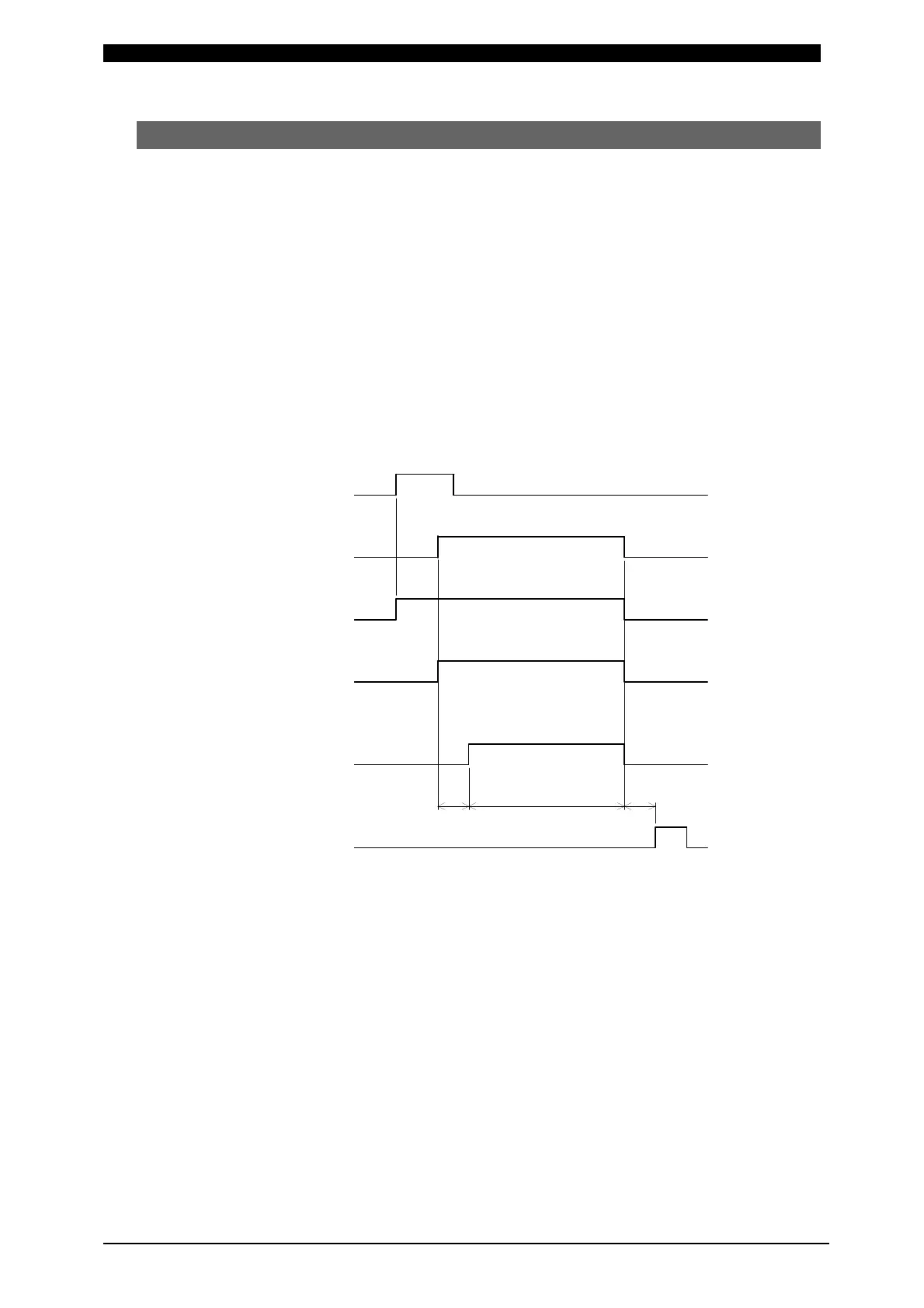
(8) Behavior in TRANS SCAN MODE
OFF Setting
It is a setting of the case where Transformer Selector MA-650A is not used.
The behavior is the same as the one in (1) Fundamental Sequence.
Those settings mentioned below in through are the ones of the case where
Transformer Selector MA-650A is used.
ON Setting
The weld current is supplied through the transformer set at the item of
Transformer No. (TR#) in SCHEDULE Screen.
Supposing that SCHEDULE No. is 2 (SCH2) and Transformer No. is 3 (TR#3),
the timing chart where the supply of weld current is started is shown as follows.
a: Transformer Changeover Time (10 ms)
b: Time period for computing a monitored value
See b: Time period for computing a monitored value at 9.(1)
Fundamental Sequence.
Because Transformer 3 (TR#3) is set for SCHEDULE #2 (SCH2), weld current
is supplied through the Transformer connected to Transformer 3 in
Transformer Selector MA-650A.
END Output OFF
SOL2 Output
SOL1 Output
2ND STAGE
1ST STAGE OFF
OFF
OFF
OFF
Transformer No.
ON Setting in Transformer Selector
Weld
SCH2
TR#3
a b
 Loading...


