IPB-5000B
10. External Communication Function
10-3
(4) Protocol
Single-directional Communication Mode
(When DATA OUTPUT is selected at COMM CONTROL in STATUS Screen)
1) Monitor Data
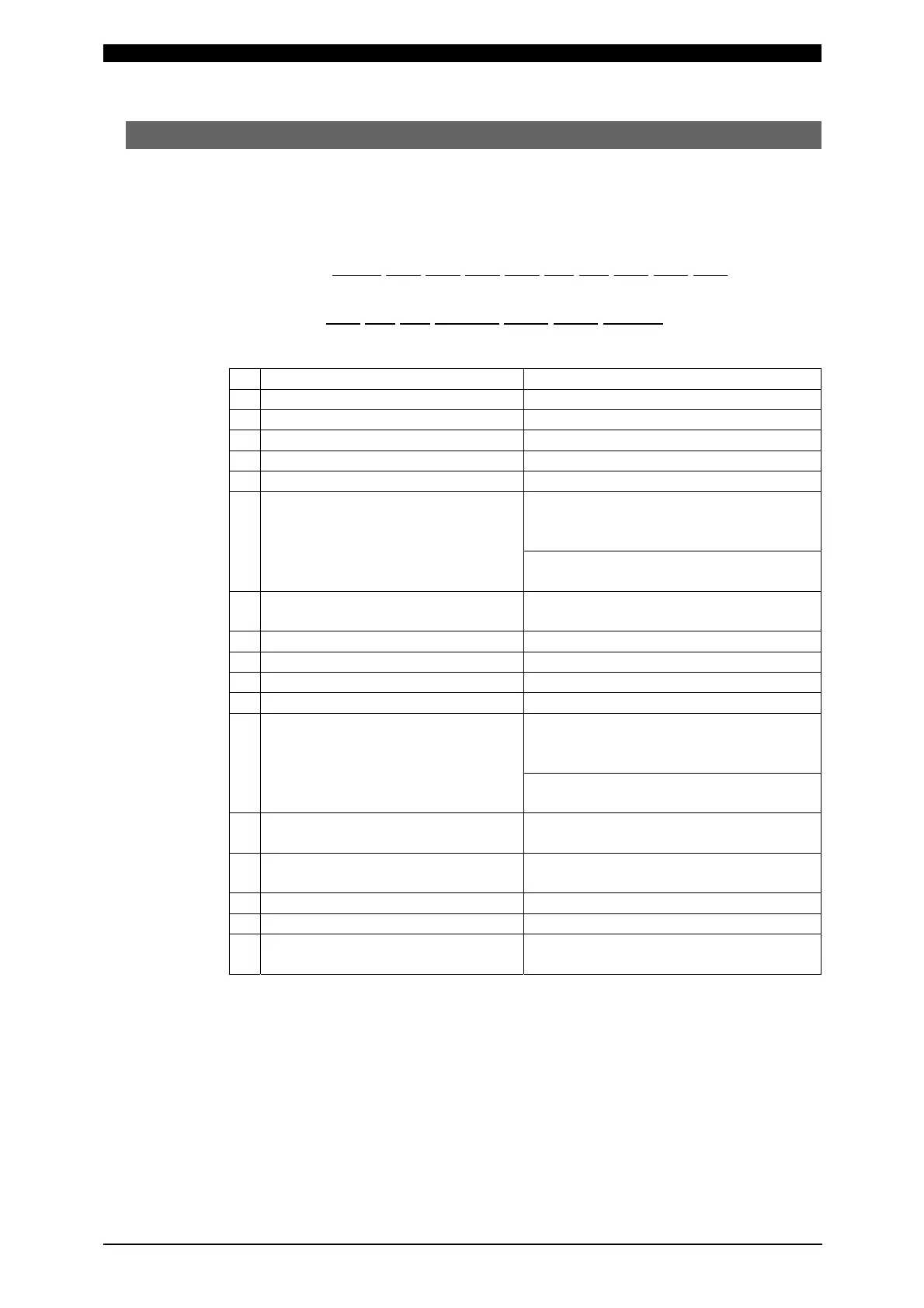
Data strings: !01001:1.49,1.51,0.51,0.55, 0.7, 0.3,2.01,2.03,0.61,
A B C D E F G
H I J K
0.55, 1.2, 0.3,+01.250,010.0,010.0,-00.300 [CR] [LF]
L
M N O P Q R
A Device No. Fixed to 2 digits (00 to 31)
B Schedule No. Fixed to 3 digits (001 to 127)
C Monitor Current of WE1 (RMS) Fixed to 4 digits (0.00 to 6.00) (kA)
D Monitor Current of WE1 (PEAK) Fixed to 4 digits (0.00 to 6.00) (kA)
E Monitor Voltage of WE1 (RMS) Fixed to 4 digits (0.00 to 9.99) (V)
F Monitor Voltage of WE1 (PEAK) Fixed to 4 digits (0.00 to 9.99) (V)
G Monitor Power of WE1 Fixed to 4 digits (0.0 to 20.0) (kW)
(CURR, VOLT, COMB, POWER-H
Control)
(NB1)
Fixed to 4 digits (0.00 to9.99) (kW)
(POWER-L Control)
H Monitor Resistance of WE1 Fixed to 4 digits (0.0 to 99.9) (mΩ)
(NB1)
I Monitor Current of WE2 (RMS) Fixed to 4 digits (0.00 to 6.00) (kA)
J Monitor Current of WE2 (PEAK) Fixed to 4 digits (0.00 to 6.00) (kA)
K Monitor Voltage of WE2 (RMS) Fixed to 4 digits (0.00 to 9.99) (V)
L Monitor Voltage of WE2 (PEAK) Fixed to 4 digits (0.00 to 9.99) (V)
M Monitor Power of WE2 Fixed to 4 digits (0.0 to 20.0) (kW)
(CURR, VOLT, COMB, POWER-H
Control)
(NB1)
Fixed to 4 digits (0.00 to9.99) (kW)
(POWER-L Control)
N Monitor Resistance of WE2 Fixed to 4 digits (0.0 to 99.9) (mΩ)
(NB1)
O Final Displacement Fixed to 7 digits (-29.999 to +29.999)
(mm)
P Weld Time of WE1 Fixed to 5 digits (000.0 to 500.0) (ms)
Q Weld Time of WE2 Fixed to 5 digits (000.0 to 500.0) (ms)
R Displacement at detecting
Workpiece
Fixed to 7 digits (-29.999 to +29.999)
(mm)
NB1: The range between 0.0 and 9.9 is output as [SP]0.0 and [SP]9.9.
 Loading...


