IPB-5000B
10. External Communication Function
10-4
2) Error Data
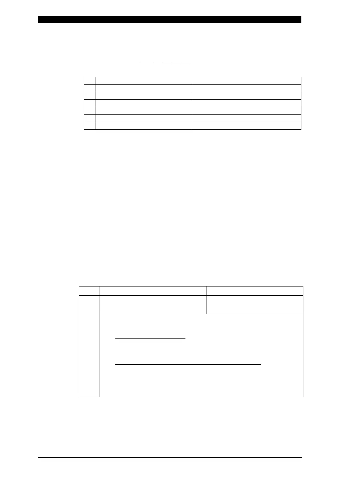
Data strings: !01001:E01,02,03,05,07[CR][LF]
A B C D E F G
A Device No. Fixed to 2 digits (00 to 31)
B Schedule No. Fixed to 3 digits (001 to 127)
(NB1)
C Error Code 1 Fixed to 2 digits (01 to 31)
D Error Code 2 Fixed to 2 digits (01 to 31)
E Error Code 3 Fixed to 2 digits (01 to 31)
F Error Code 4 Fixed to 2 digits (01 to 31)
G Error Code 5 Fixed to 2 digits (01 to 31)
The number of Error Codes is of five Max. In the case of only one error code,
the error codes D to G are omitted.
NB1: When a setting for consecutive weldings is selected in TANS SCAN
MODE, the schedule number of the last occurred error is sent.
Bi-directional Communication Mode
(When BI-DIRECTION is selected at COMM CONTROL in STATUS Screen)
Description of Symbols
ID1, ID2: Shows Device No.
Fixed to 2 digits (ID1=Ten’s place, ID2=One’s place)
SH1, SH2, SH3: Shows Schedule No.
Fixed to 3 digits (SH1=Hundred’s place, SH2=Ten’s place,
SH3=One’s place)
CD1, CD2, CD3: Shows Specified Code.
CD1------------Alphabet Classified Symbol
CD2, CD3----Code Classified Number
(See (5)Specified Code for details of codes.)
No. Description of Command Code
1
Inquiry about Model and ROM
Version
# Device No. I
Example: Read model of Device No. 1 and ROM Version
From Host PC to IPB-5000B
# ID1 ID2 I CR LF
(# 0 1 I CR LF)
From IPB-5000B to Host PC
! ID1 ID2 : IPB-5000B , ROM Version CR LF
(! 0 1 : IPB-5000B , ROM Version CR LF)
Note) When “*” is set for both ID1 and ID2, all connected devices
respond. In the case that all devices respond, the time-lag of
response is 100 ms multiplied by ID No. (Device No.).
 Loading...


