EasyManua.ls Logo

Amana AMV9 User Manual

Amana AMV9
40 pages
To Next Page IconTo Next Page
Page #1 background imageLoading...
Page #1 background image
© 2004-2006 Goodman Company, L.P.
Installer: Affix all manuals adjacent to the unit.
INSTALLATION INSTRUCTIONS
AMV9/ACV9
T
WO
-S
TAGE
V
ARIABLE
S
PEED
GAS
-
FIRED
WARM
AIR
FURNACE
IO-253H
*NOTE: Please contact your distributor or our
website for the applicable product data book
referred to in this manual.
ATTENTION INSTALLING PERSONNEL
As a professional installer you have an obligation to know the product better than the customer. This includes all safety
precautions and related items.
Prior to actual installation, thoroughly familiarize yourself with this Instruction Manual. Pay special attention to all safety
warnings. Often during installation or repair it is possible to place yourself in a position which is more hazardous than
when the unit is in operation.
Remember, it is your responsibility to install the product safely and to know it well enough to be able to instruct a
customer in its safe use.
Safety is a matter of common sense...a matter of thinking before acting. Most dealers have a list of specific good safety
practices...follow them.
The precautions listed in this Installation Manual are intended as supplemental to existing practices. However, if there is
a direct conflict between existing practices and the content of this manual, the precautions listed here take precedence.
(Type FSP CATEGORY IV Direct or Non Direct Vent Air Furnace)
RECOGNIZE THIS SYMBOL AS A SAFETY PRECAUTION.
These furnaces comply with requirements
embodied in the American National Standard
/ National Standard of Canada ANSI
Z21.47·CSA-2.3 Gas Fired Central Furnaces.
C
US
®
07/06
®
is a trademark of Maytag Corporation and is used under
license to Goodman Company, L.P. All rights reserved.
www.amana-hac.com

Table of Contents

Question and Answer IconNeed help?

Do you have a question about the Amana AMV9 and is the answer not in the manual?

Amana AMV9 Specifications

General IconGeneral
ModelAMV9
Efficiency RatingUp to 96% AFUE
Ignition TypeHot Surface Ignition
Fuel TypeNatural Gas or Propane
Heating Capacity40, 000 to 120, 000 BTU
Blower MotorVariable-speed
Heat ExchangerStainless steel
WarrantyLimited lifetime warranty on heat exchanger, 10-year limited warranty on parts

Summary

Installation Safety and Precautions

Attention Installing Personnel

Key safety guidance for installers, emphasizing product knowledge and safe practices.

Component Identification

Safety Guidelines

Electrostatic Discharge (ESD) Precautions

Procedures to prevent damage to electronic components from static discharge.

Product Application

Location Requirements

General Location Guidelines

Criteria for selecting an appropriate and safe installation location.

Clearances and Accessibility

Minimum clearances required around the furnace for safe operation and servicing.

Combustion and Ventilation Air Requirements

Thermostat Location

Guidelines for optimal placement of the thermostat for accurate temperature control.

Installation Positions

Horizontal Applications

Propane Gas and High Altitude Installations

Vent/Flue Pipe and Combustion Air Pipe

General Venting Practices

Essential guidelines for proper installation and sizing of vent and combustion air piping.

Termination Locations

Specifies safe and code-compliant termination points for vent and air intake pipes.

Standard Furnace Connections

Instructions for using the standard factory-provided vent and air intake connections.

Direct Vent (Dual Pipe) Piping

Instructions for installing dual-pipe systems for direct vent furnaces.

Condensate Drain Lines and Drain Trap

General Condensate Management

Procedures for managing condensate generated by the high-efficiency furnace.

Upright Installation Drain Connections

Detailed steps for connecting drain hoses in upright furnace installations.

Horizontal Installation Drain Connections

Steps for connecting drain hoses in horizontal furnace installations.

Electrical Connections

115 Volt Line Connections

Instructions for connecting the main 115V power supply to the furnace.

Wiring Harness and Junction Box

Details on the furnace's wiring harness and relocating the junction box for side connections.

24 Volt Thermostat Wiring

Guidance on wiring the thermostat and other low-voltage accessories to the control module.

Single-Stage Thermostat Application

How to use a single-stage thermostat with the two-stage furnace, including delay settings.

Gas Supply and Piping

General Gas Supply Requirements

Specifications for gas type, pressure, and manifold settings for safe operation.

Gas Piping Connections

Proper methods for connecting the gas supply line to the furnace, including safety measures.

Propane Gas Conversion and Piping

Instructions for converting to propane gas and guidelines for propane gas piping.

Circulating Air and Filters

Ductwork and Airflow Design

Guidance on designing ductwork for optimal airflow and performance with the furnace.

Filter Requirements and Installation

Details on filter types, sizes, and installation procedures for proper air quality and furnace protection.

Startup Procedure and Adjustment

Furnace Startup and Operation

Step-by-step instructions for safely starting up and operating the furnace.

Gas Supply Pressure Measurement

Procedure for measuring and adjusting the incoming gas supply pressure.

Gas Manifold Pressure Measurement

Procedure for measuring and adjusting the gas valve manifold pressure for optimal operation.

Temperature Rise Measurement

How to measure and adjust the temperature rise for proper heat exchanger operation.

Circulator Blower Speeds

Guidance on selecting and setting blower speeds for optimal heating and cooling performance.

Normal Sequence of Operation

Heating Mode Operation

Sequence of events during furnace power-up and the heating cycle operation.

Cooling and Fan Only Modes

Operational sequences for cooling mode and fan-only operation.

Operational Checks

Burner Flame Inspection

Visual checks for proper burner flame characteristics during operation.

Safety Circuit Description

Integrated Control Module

Explanation of the control module's role in monitoring safety circuits and providing diagnostics.

Safety Limit Controls

Description of primary, auxiliary, and rollout limits, pressure switches, and flame sensor.

Troubleshooting

Diagnostic Chart and Lockout Reset

Guides for identifying and resolving furnace operational problems using diagnostic codes.

Maintenance

Annual Inspection

Recommended annual checks for all furnace components to ensure proper working order.

Filter Maintenance and Removal

Guidance on filter selection, cleaning/replacement, and removal procedures.

Internal Filter Removal

Bottom Return Filter Removal

Steps to remove the filter located at the bottom return opening of the furnace.
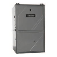
Before Leaving an Installation

Repair and Replacement Parts

Wiring Diagram

Related product manuals