SYSTEM OPERATION
11
This section gives a basic description of cooling unit operation,
its various components and their basic operation. Ensure your
system is properly sized for heat gain and loss according to
methods of the Air Conditioning Contractors Association (ACCA)
or equivalent.
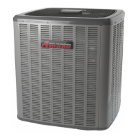
CONDENSING UNIT
The condenser air is pulled through the condenser coil by a di-
rect drive propeller fan. This condenser air is then discharged
out of the top of the cabinet. These units are designed for free air
discharge, so no additional resistance, like duct work, shall be
attached.
The suction and liquid line connections on present models are of
the sweat type for field piping with refrigerant type copper. Front
seating or ball valves are factory installed to accept the field run
copper. The total refrigerant charge for a normal installation is
factory installed in the condensing unit.
AVXC20 models are available in 2 through 5 ton sizes and use R-
410A refrigerant. They are designed for 208/230 volt single phase
applications.
AVXC20 2-4 ton R-410A model units use a Daikin rotary compres-
sor, while the 5 ton has a Daikin Scroll compressor. Both
compressor types are specifically designed for R-410A refriger-
ant. These models are ComfortNet
TM
ready.
There are a number of design characteristics which are different
from the traditional reciprocating and/or scroll compressors.
AVXC20 models use "PVE" which is NOT compatible with mineral
oil based lubricants like 3GS. "PVE" oil (required by the manufac-
turer) must be used if additional oil is required.
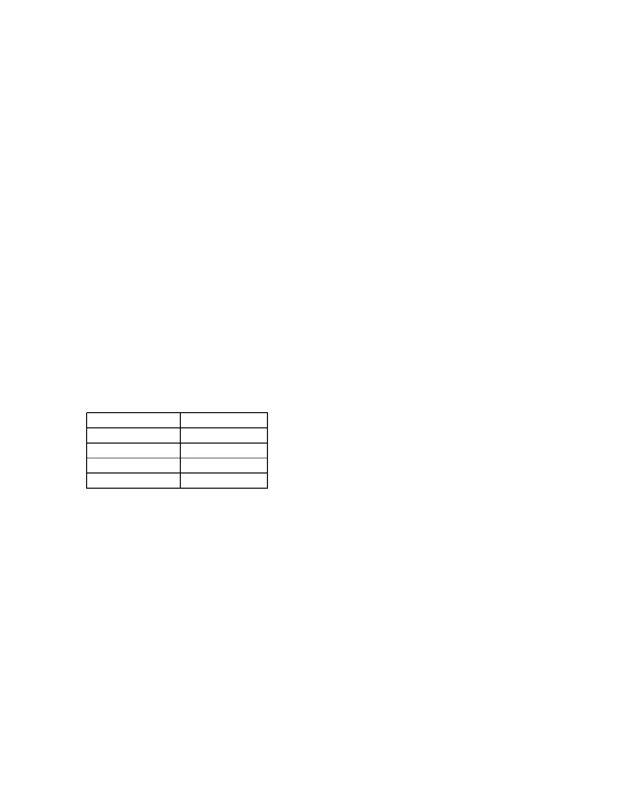
Model Name Compressor Oil
AVXC200241** PVC50K
AVXC200361** PVC50K
AVXC200481** PVC50K
AVXC200601** FVC68D
COOLING
The refrigerant used in the system is R-410A. It is a clear, color-
less, non-toxic and non-irritating liquid. R-410A is a 50:50 blend
of R-32 and R-125. The boiling point at atmospheric pressure is
-62.9°F.
A few of the important principles that make the refrigeration cycle
possible are: heat always flows from a warmer to a cooler body.
Under lower pressure, a refrigerant will absorb heat and vapor-
ize at a low temperature. The vapors may be drawn off and con-
densed at a higher pressure and temperature to be used again.
The indoor evaporator coil functions to cool and dehumidify the
air conditioned spaces through the evaporative process taking
place within the coil tubes.
NOTE: The pressures and temperatures shown in the refrigerant
cycle illustrations on the following pages are for demonstration
purposes only. Actual temperatures and pressures are to be ob-
tained from the "Expanded Performance Chart".
Liquid refrigerant at condensing pressure and temperatures leaves
the outdoor condensing coil through the drier and is metered into
the indoor coil through the metering device. As the cool, low pres-
sure, saturated refrigerant enters the tubes of the indoor coil, a
portion of the liquid immediately vaporizes. It continues to soak
up heat and vaporizes as it proceeds through the coil, cooling the
indoor coil down to about 48°F.
Heat is continually being transferred to the cool fins and tubes of
the indoor evaporator coil by the warm system air. This warming
process causes the refrigerant to boil. The heat removed from the
air is carried off by the vapor.
As the vapor passes through the last tubes of the coil, it becomes
superheated. That is, it absorbs more heat than is necessary to
vaporize it. This is assurance that only dry gas will reach the
compressor. Liquid reaching the compressor can weaken or break
compressor valves.
The compressor increases the pressure of the gas, thus adding
more heat, and discharges hot, high pressure superheated gas
into the outdoor condenser coil.
In the condenser coil, the hot refrigerant gas, being warmer than
the outdoor air, first loses its superheat by heat transferred from
the gas through the tubes and fins of the coil. The refrigerant now
becomes saturated, part liquid, part vapor and then continues to
give up heat until it condenses to a liquid alone. Once the vapor is
fully liquefied, it continues to give up heat which subcools the
liquid, and it is ready to repeat the cycle.
The inverter system can stop the compressor or outdoor fan to
protect the unit. The inverter system can run higher compressor
speed than required from thermostat to recover compressor oil
that flows.
 Loading...