Component Testing Procedures
!
WARNING
To avoid risk of electrical shock, personal injury or death, disconnect power to oven and discharge capacitor
before servicing, unless testing requires power.
July 2006 16027356
©2006 Maytag Services Replaces 16026912
3
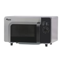
Illustration Component Test Results
208
COM
230
120
Auto Transformer
230
208
120
0
Discharge Capacitors
Remove all wires from terminals.
Measure resistance from:
230 to 0.........................................................
208 to 0.........................................................
120 to 0.........................................................
42.4 Ω.
38.6 Ω.
21.5 Ω.
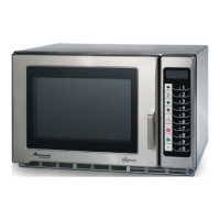
1
2
3
4
7
6
5
8
Terminal 1
- 230 V
Terminal 2
- Common
Terminal 3
- 208 V
Transformer
# 4
# 1
# 3
# 2
# 5
# 6
# 7
# 8
1.0 F
-300 MA
-300 MA
1.0 F
Discharge Capacitors
Remove all wires from terminals.
Measure resistance from:
Terminal 1 to 2..............................................
Terminal 1 to 3..............................................
Terminal 5 to 6..............................................
Terminal 7 to 8..............................................
Terminal 4 to Ground screw on transformer ..
Terminal 4 to any other terminal....................
Gray
Violet
Red
12
3
1.0 Ω.
Less than 1 Ω.
Less than 1 Ω.
Less than 1 Ω.
30 Ω.
Infinite resistance. If not, replace
transformer.
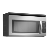
Primary /
Logic
Secondary
Mo nitor
Interlock switch
assembly
Disconnect wires to switch.
With door open measure resistance from:
Terminal C to NC Monitor ........................
Terminal C to NO Primary / Logic ............
Terminal C to NO Secondary ...................
With door closed measure resistance from:
Terminal C to NC Monitor ........................
Terminal C to NO Primary / Logic ............
Terminal C to NO Secondary ...................
Door Closed
Primary / Logic
C
NC
NO
C
C
NO
Secondary
Monitor
Continuity.
Infinite.
Infinite.
Infinite.
Continuity.
Continuity.
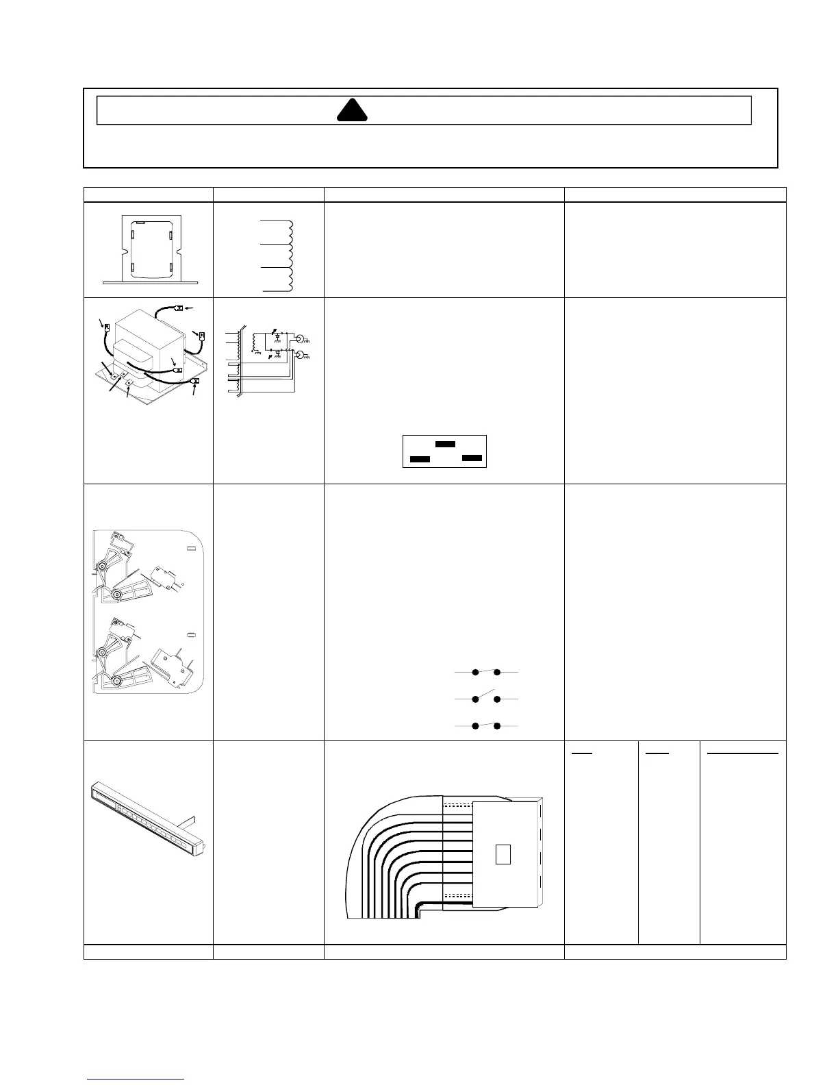
Touch Panel
Assembly
Continuity is indicated as 100 Ω and below.
Pin 1: Ground.
Pad
1
2
3
4
5
6
7
8
9
0
Start
Stop/Reset
Power Level
X 2
Time Entry
Pins
8 & 10
7 & 10
6 & 10
5 & 10
4 & 10
3 & 10
8 & 9
7 & 9
6 & 9
5 & 9
4 & 9
4 & 8
5 & 8
6 & 8
7 & 8
Measurement
Continuity
Continuity
Continuity
Continuity
Continuity
Continuity
Continuity
Continuity
Continuity
Continuity
Continuity
Continuity
Continuity
Continuity
Continuity
Wire Harness Test continuity of wires..................................
Continuity.
 Loading...