EasyManua.ls Logo

Amana GUCA090AX40 User Manual

Amana GUCA090AX40
78 pages
To Next Page IconTo Next Page
Page #1 background imageLoading...
Page #1 background image
Service
Instructions
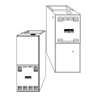
40" 90% Condensing Gas Furnaces
GUCA, GCCA & Accessories
This manual is to be used by qualified HVAC
technicians only. Amana does not assume
any responsibility for property damage or
personal injury for improper service proce-
dures done by an unqualified person.
RS6610002
Revision 0
October 1998
A
higher standard of comfor
t
Heating
n
Air Conditioning
®
Model and Manufacturing
numbers listed on page 4.

Questions and Answers:

Amana GUCA090AX40 Specifications

General IconGeneral
BrandAmana
ModelGUCA090AX40
CategoryFurnace
Fuel TypeNatural Gas
Heating Capacity90, 000 BTU
AFUE80%
BTU Input90, 000
StagesSingle Stage
Blower Motor TypePSC
TypeGas
BTU Output72, 000 BTU
Output BTU72, 000 BTU
WarrantyLimited Lifetime

Summary

IMPORTANT INFORMATION

IMPORTANT NOTICES

Warnings and cautions for service procedures regarding unqualified personnel and liability.

SAFETY SYMBOLS AND LABELS

Explanation of danger, warning, and caution symbols and their meanings.

PRODUCT IDENTIFICATION

FURNACE ACCESSORY KITS

List of available accessory kits for furnaces including twinning and altitude kits.

ADDITIONAL FURNACE ACCESSORIES

List of other available furnace accessories like air cleaners and filter racks.

MODEL NUMBER BREAKDOWN AND EXPLANATION

Detailed explanation of furnace model number coding for identification.

SAFETY WARNINGS AND OPERATING INSTRUCTIONS

Crucial safety precautions for operation and step-by-step startup guide.

UNIT DIMENSIONS AND CLEARANCES

Physical dimensions and minimum clearances to combustible materials.

COMPONENT IDENTIFICATION

Labeled diagrams identifying key furnace components for upflow and counterflow models.

COIL MATCHES FOR FURNACES

Chart matching furnace models with compatible Amana evaporator coils.

ACCESSORIES: FLOOR BASES AND FILTER RACKS

Details on floor bases and external filter rack kits with dimensions.

ACCESSORIES: MEDIA AND ELECTRONIC AIR CLEANERS

Specifications and usage for MAC1 Media Air Cleaner and EAC5 Electronic Air Cleaner.

ACCESSORIES: CONCENTRIC VENT KITS

Information on concentric vent conversion kits for specific furnace models.

FURNACE SPECIFICATIONS

GUCA MODEL SPECIFICATIONS

Detailed technical specifications for GUCA series furnaces.

GCCA MODEL SPECIFICATIONS

Detailed technical specifications for GCCA series furnaces.

BLOWER PERFORMANCE SPECIFICATIONS

GUCA/GCCA BLOWER PERFORMANCE DATA

Airflow (CFM) versus external static pressure data for blower speed selection.

BTU OUTPUT VS TEMPERATURE RISE CHART

Chart relating BTU output, CFM, and temperature rise for performance analysis.

COMBUSTION AND VENTILATION AIR

AIR REQUIREMENTS AND CODE SECTIONS

NFPA code requirements for air supply for combustion and ventilation.

EQUIPMENT LOCATION AND VENTING DIAGRAMS

Diagrams illustrating air supply methods in confined spaces per code.

PIPING PRACTICES AND MATERIALS

Guidelines for vent/flue pipe and combustion air pipe materials and installation.

TERMINATION LOCATIONS AND CANADIAN REQUIREMENTS

Restrictions for vent pipe terminations and Canadian venting codes.

FURNACE AND PIPING CONNECTIONS

Standard and alternate connection methods for vent/flue and combustion air piping.

VENT/FLUE PIPE CUTS AND ALTERNATE LOCATIONS

Procedures for cutting vent pipe and using alternate installation locations.

COMBUSTION AIR INTAKE AND NON-DIRECT VENT PIPING

Details on combustion air intake, non-direct vent piping, and pipe lengths.

NON-DIRECT VENT TERMINATIONS

Guidelines for single-pipe vent and combustion air terminations.

DIRECT VENT PIPING AND TERMINATIONS

Guidelines for dual-pipe venting and termination requirements.

CONCENTRIC VENT TERMINATION

Details on concentric vent kit installation for direct vent furnaces.

CONDENSATE DRAIN LINES AND DRAIN TRAP

GENERAL DRAINAGE AND INSTALLATION GUIDELINES

Requirements for condensate drainage, trap priming, and drain line slope.

UPRIGHT DRAIN HOSE CONNECTIONS

Connecting drain hoses for upright installations using standard vent/flue outlets.

ALTERNATE UPRIGHT DRAIN HOSE CONNECTIONS

Connecting drain hoses for upright installations using alternate vent/flue outlets.

HORIZONTAL DRAIN CONNECTIONS AND TRAP MOUNTING

Drain hose routing and trap mounting for horizontal units.

PRODUCT DESIGN

SAFETY AND ESD PRECAUTIONS

Warnings regarding electrical safety, static discharge, and product use limitations.

LOCATION REQUIREMENTS AND CONSIDERATIONS

Guidelines for selecting furnace installation location and environmental factors.

FURNACE SUSPENSION AND HORIZONTAL INSTALLATIONS

Methods for suspending furnaces and considerations for horizontal mounting.

INSTALLATION PROCEDURES AND ELECTRICAL CONNECTIONS

Details on alternate connections, electrical hookups, and wiring harness.

GAS SUPPLY AND PIPING

General information on gas supply, types, pressure, and conversion kits.

PROPANE CONVERSION AND GAS PIPING DETAILS

Propane conversion, gas valve operation, and detailed piping procedures.

FILTER SIZING AND LOCATIONS

Filter selection, placement options, and startup procedures.

FURNACE OPERATION, STARTUP, AND SHUTDOWN

Step-by-step procedures for furnace operation, startup, and shutdown.

CIRCULATOR BLOWER SPEED ADJUSTMENT

Guide for adjusting blower speeds for heating and cooling requirements.

SYSTEM OPERATION

NORMAL OPERATIONAL SEQUENCES

Step-by-step sequences for power up, heating, cooling, and fan modes.

TIMING CHARTS

Visual timing diagrams for normal heating and cooling operations.

TROUBLESHOOTING AND LOCKOUT RESET

Procedures for diagnosing system issues and resetting furnace lockout.

TROUBLESHOOTING CHART

Comprehensive chart of symptoms, causes, and corrective actions for furnace faults.

POLARIZATION AND PHASING

CHECKING TRANSFORMER PHASE AND POLARITY

Methods for verifying electrical phase and polarity of transformers.

MAINTENANCE

ANNUAL INSPECTION AND AIR FILTER REPLACEMENT

Recommended annual inspection tasks and air filter maintenance procedures.

COMPONENT MAINTENANCE (BLOWERS, DRAINAGE, FLUE, BURNERS, SENSOR)

Maintenance procedures for blowers, condensate system, flue passages, burners, and sensors.

SERVICING

TEST EQUIPMENT AND HEATING PERFORMANCE TESTING

Essential tools and procedures for heating performance tests.

GAS RATE CHARTS AND TROUBLESHOOTING GUIDE

Gas rate tables and a general troubleshooting guide structure.

SERVICING SECTION INDEX

An index of all servicing procedures and their corresponding page numbers.

ELECTRICAL AND THERMOSTAT CHECKS

Procedures for checking voltage, wiring, thermostat, and anticipator.

TRANSFORMER, LIMIT CONTROLS, AND BLOWER CHECKS

Tests for transformer, primary/auxiliary limits, and blower motor.

CAPACITOR AND GAS VALVE CHECKS

Procedures for testing capacitors and gas valves.

BURNER, ORIFICE, AND GAS PRESSURE CHECKS

Checks for main burners, orifices, and gas pressure.

DELAYED IGNITION AND FLASH-BACK CHECKS

Procedures for diagnosing delayed ignition and flashback issues.

DUCT STATIC AND TEMPERATURE RISE CHECKS

Methods for measuring duct static and temperature rise.

PRESSURE SWITCH AND HIGH ALTITUDE CONSIDERATIONS

Testing pressure controls and high altitude installation requirements.

IGNITER AND CONTROL MODULE CHECKS

Procedures for checking mini igniters and ignition control modules.

FLAME SENSOR AND CONTROL OPERATION CHECKS

Testing the flame sensor and ignition control operation.

FLAME ROLLOUT SWITCH CHECKS

Testing procedures for the flame rollout safety switch.

HEAT EXCHANGER ASSEMBLY REPLACEMENT

Detailed procedures for removing and replacing the heat exchanger assembly.

WIRING DIAGRAMS

GUCA MODEL WIRING DIAGRAM

Electrical wiring diagram for GUCA series furnaces.

GCCA MODEL WIRING DIAGRAM

Electrical wiring diagram for GCCA series furnaces.

SCHEMATICS

GUCA FURNACE SCHEMATIC

Typical schematic for GUCA models with integrated ignition control.

GCCA FURNACE SCHEMATIC

Typical schematic for GCCA models with integrated ignition control.

FURNACE TWINING KIT SCHEMATIC

Schematic for the FTK03A furnace twinning kit.

Related product manuals