Component Specifications
!
WARNING
To avoid risk of electrical shock, personal injury or death; disconnect power to oven and discharge capacitor before
servicing, unless testing requires power.
18
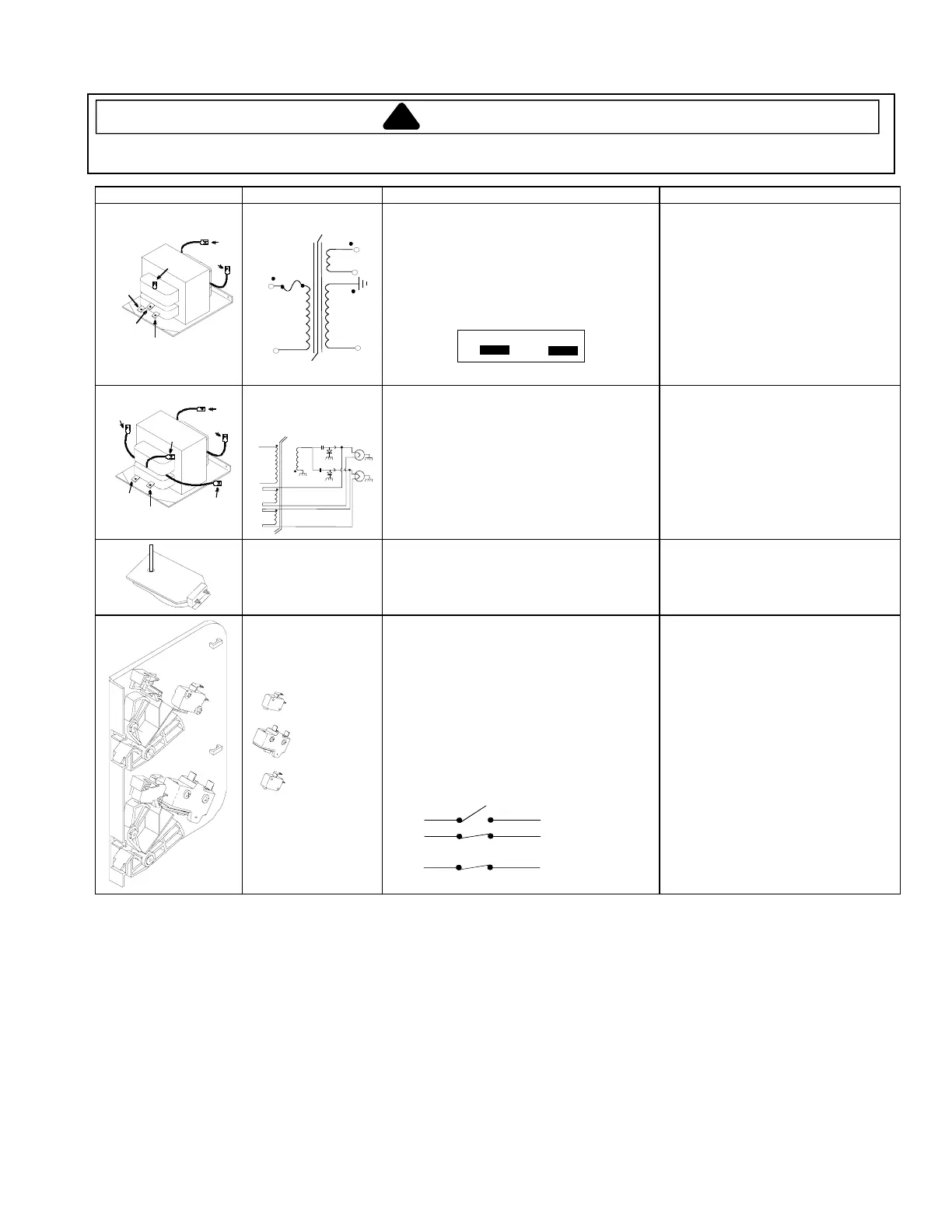
Illustration Component Testing Results
COM
220
230
4
6
5
Transformer
1100 Watt
4
3
5
6
(COM)
1
(230V)
Discharge Capacitor
Remove all wires from terminals, and
measure resistance from:
220 to Common............................................
230 to Common............................................
Terminal 5 to 6..............................................
Terminal 4 to Earth screw on transformer....
Terminal 4 to any other terminal ..................
Gray Pink
1
3
This transformer is equipped with a
155° C thermal cutout.
1.3 Ω.
1.3 Ω.
<1 Ω.
70 Ω.
Infinite resistance. If not, replace
transformer.
COM
230
4
7
6
5
8
Transformer – 1400,
1800, and 2100
Watt
#
4
#
1
#
2
#
5
#
6
#
7
#
8
Discharge Capacitor
Remove all wires from terminals, and
measure resistance from:
230 to Common............................................
Terminal 5 to 6..............................................
Terminal 7 to 8..............................................
Terminal 4 to Earth screw on transformer....
Terminal 4 to any other terminal ..................
1 Ω.
<1 Ω.
<1 Ω.
38 - 45 Ω
± 5%.
Infinite resistance. If not, replace
transformer.
Stirrer motor Remove all wires from motor.
Measure resistance across terminals ..............
Approximately 12 KΩ.
Interlock switch
assembly
Primary
Secondary
Monitor
Disconnect wires to switch.
With door open measure resistance from:
Terminal C to NO Primary.......................
Terminal C to NO Secondary ..................
Terminal C to NC Monitor........................
With door closed measure resistance from:
Terminal C to NO Primary.......................
Terminal C to NO Secondary ..................
Terminal C to NC Monitor........................
Door Closed
C
C
C
NC
NO
NO
Primary
Secondary
Monitor
Infinite.
Infinite.
Continuity.
Continuity.
Continuity.
Infinite.