20
position) and install it on the right side (top) collector
box drain port.
12. Install the non-grommet end of hose #11 from
outside the cabinet in the upper drain hole. Install on
collector box and secure with a silver clamp.
13. Use two silver clamps and secure the hoses to drain
trap. The trap outlet faces the front of the furnace.
Secure the trap to the cabinet using two screws
removed in step 2 by inserting the two screws through
the large set of holes in the top mounting tabs of the
trap into the two predrilled holes in the side of the
cabinet.
14. Refer to Field Supplied Drain section for instructions
on eld supplied / installed drain on outlet of furnace
trap.
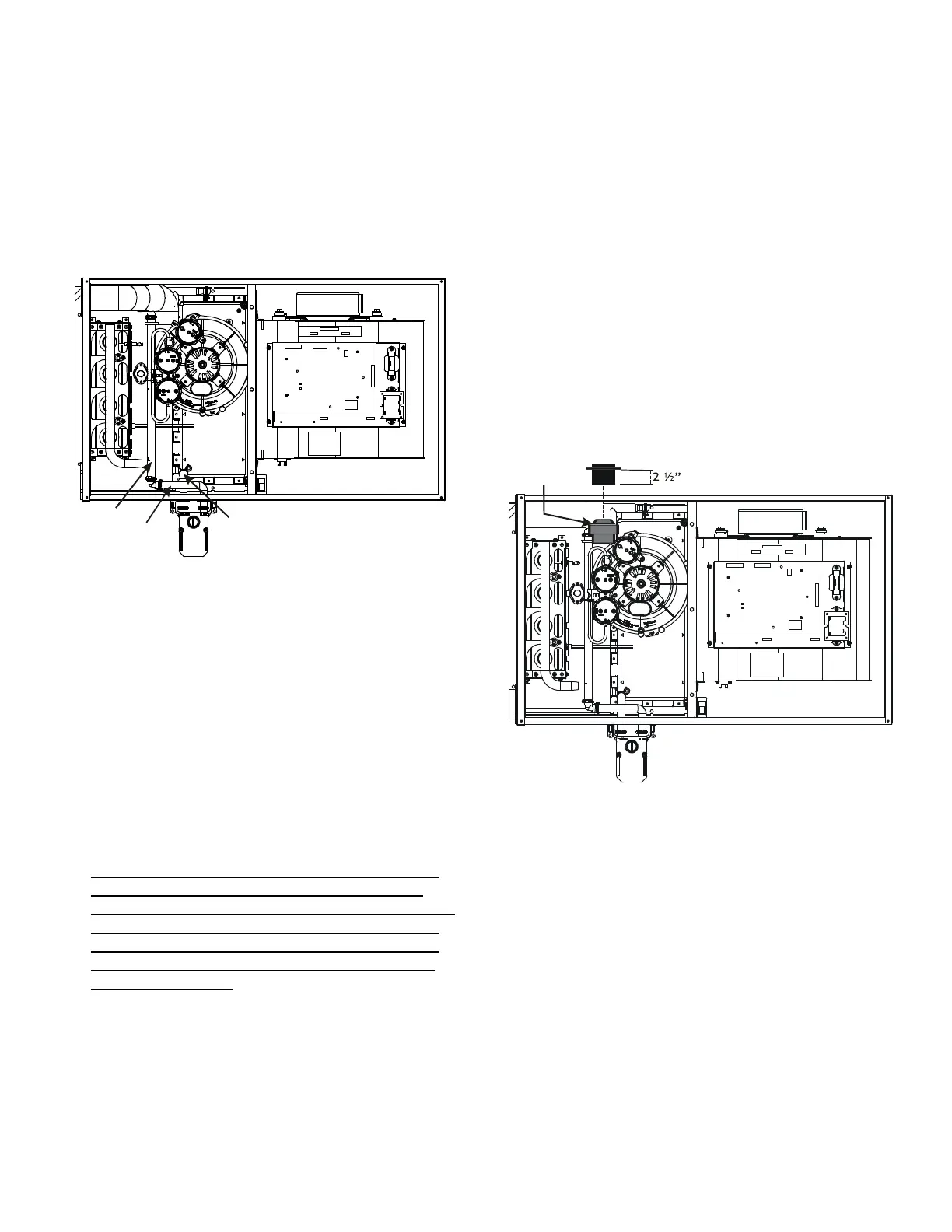
* Also see the Front Cover Pressure Switch Tube Location.
Insert flange. Cut 2 ½” long.
R 000142F
1. (Draining the RF000142 Coupling) Locate hose #2
(factory installed). Cut o and discard the 45°radius
end.
2. Install 90°radius end of hose #2 on RF000142 drain
outlet and secure with a red clamp.
3. Insert coupling in hose #2 and secure with a red
clamp.
4. Locate hose #5 and cut 3” from the non-grommet end.
Discard the section without the grommet.
5. Insert the cut end of tube #5 through the lower cabinet
drain hole.
6. Insert 100 degree elbow in the cut end of hose #5.
7. Locate hose #6. Using red clamps, connect between
the coupling and 100 degree elbow, cutting o excess
tubing.
8. (Draining the Collector Box) Remove cap from left
side collector box drain port (bottom in horizontal left
position) and install it on right side (top) collector box
drain port.
8. Refer to Field Supplied Drain section for instructions
on eld supplied/nstalled drain on outlet of furnace
trap.
½
10
1. Remove the clamps from the two drain tubes on the
trap.
2. Remove the two screws holding the drain trap to the
blower deck.
3. Remove the trap and hoses from the blower deck .
4. Remove the two plugs from the left side of the cabinet
and install them in the blower deck.
5. (Draining the Vent Elbow) Locate hose #6. Measuring
from the non-grommet end; cut o and discard 1 ½”
for a “D” width cabinet, 5” for a “C” width cabinet, 8 ½”
for a “B” width cabinet.
6. Remove the rubber plug from vent – drain elbow side
port. Place hose #6 on the vent – drain elbow side
port and secure with a silver clamp .
8. Locate hose #5 and cut 3” from the non-grommet end.
Discard the section without the grommet.
9. Insert the cut end of tube #5 through the lower cabinet
drain hole.
10. Connect hose #6 & hose #5 using 100º elbow and
secure with two red clamps
11. (Draining the Collector Box) Remove cap from left
side collector box drain port (bottom in horizontal left
 Loading...