28
diering lter arrangements can be applied. Filters can
be installed in the central return register or a side panel
external lter rack kit (upows). As an alternative a media
air lter or electronic air cleaner can be used as the
requested lter. Consider installing an air cleaner with
deep-pleated media lter at the time of furnace installation.
A deep-pleated lter with a MERV rating of 8 (minimum)
will often provide better ltration to protect equipment and
the air distribution system than a standard 1” lter and
often has lower static pressure loss than a 1” lter. Also
a deep-pleated lter will typically require less frequent
replacement intervals. Avoid using highly restrictive 1”
lters which produce static pressure loss greater than .25”
W.C. In some installations the minimum lter size required
will not lend itself to a lter installation on the side of the
furnace. The installation of a centrally installed air cleaner
cabinet or a return duct lter installation may oer more
practicality.
Clean Comfort™ brand MERV 11 air cleaners have
5¼” media lters and are available in the following
congurations. Consult your distributor for information on
our complete line of IAQ Clean Comfort™ products.
Minimum Recommended Filter Size^
*MVC960403BN* 1 - 16 X 25 Side or Bottom
*MVC960603BN* 1 - 16 X 25 Side or Bottom
*MVC960803BN* 1 - 16 X 25 Side or Bottom
*MVC960804CN* 1 - 16 X 25 Side or Bottom
*MVC961005CN* 1 - 20 X 25 Bottom / 2 - 16 X 25 Side Return
*MVC961005DN* 1 - 20 X 25 Bottom / 2 - 16 X 25 Side Return
*MVC961205DN* 1 - 20 X 25 Bottom / 2 - 16 X 25 Side Return
*CVC960403BN* 2 - 10 X 20 or 1 - 16 X 25 Top Return
*CVC960603BN* 2 - 10 X 20 or 1 - 16 X 25 Top Return
*CVC960804CN* 2 - 10 X 20 or 1 - 16 X 25 Top Return
*CVC961005CN* 2 - 14 X 20 or 1 - 20 X 25 Top Return
*CVC961205DN* 2 - 14 X 20 or 1 - 20 X 25 Top Return
^
Larger fi l ters ma y be us ed, fi l ters may a l s o be centra l l y located
WARNING
When the furnace is installed without a cooling coil, it is
recommended that a removable access panel be provided
in the outlet air duct. This opening shall be accessible
when the furnace is installed and shall be of such a size
that the heat exchanger can be viewed for visual light
inspection or such that a sampling probe can be inserted
into the airstream. The access panel must be made to
prevent air leaks when the furnace is in operation.
When the furnace is heating, the temperature of the return
air entering the furnace must be between 55°F and 100°F.
CUT USING TIN SNIPS
SCRIBE LINES OUTLINING
DUCT FLANGES
Filters must be used with this furnace. Discuss lter
maintenance with the building owner. Filters do not ship
with this furnace, but must be provided, sized and installed
externally by the installer. Filters must comply with UL900
or CAN/ULCS111 standards. Damage or repairs due to
the installation of the furnace without lters is not covered
under the warranty.
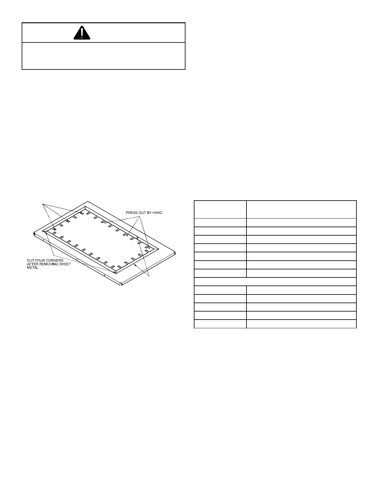
On upow units, guide dimples locate the side return cutout
locations. Use a straight edge to scribe lines connecting
the dimples. Cut out the opening on these lines.
Filters must be installed in either the central return register
or in the return air duct work.
Depending on the installation and/or customer preference,
 Loading...