SERVICING
66
If the pressure switch opens before the ignition period, the
induced draft blower will remain on and the control will stay in
pre-purge until the pressure switch is closed for an entire 15
second pre-purge period. The LED will flash a code of "2" to
indicate open pressure switch.
If the pressure switch opens after the gas valve has been
energized, the control will de-energize the gas valve and run
the indoor blower through the heat off delay. The inducer
stays on until the pressure switch re-closes. Then the con-
trol makes another ignition attempt.
WARNING
HIGH
VOLTAGE
D
ISCONNECT
ALL
POWER BEFORE SERVICING OR
INSTALLING THIS UNIT.
MULTIPLE POWER SOURCES MAY
BE PRESENT.
F
AILURE TO DO SO MAY CAUSE PROPERTY
DAMAGE, PERSONAL INJURY OR DEATH.
1. Remove wires from the electrical terminals.
2. Using a VOM check from Common to NO (Normally
Open) - should read open.
If switch reads as noted proceed to Step 3, otherwise re-
place control.
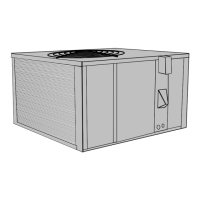
3. Remove the pressure control hose from the control and
interconnect with an inclined manometer as shown:
PRESSURE SWITCH
INCLINED
MANOMETER
1/4" COPPER TEE
HOSE
TO J-TUBE
Reconnect wires VT-18 to Common and YL-11 to NO termi-
nals.
With Power ON:
WARNING
L
INE VOLTAGE NOW PRESENT.
4. Energize furnace for heating cycle. The induced draft
blower motor will begin to run. The inclined manometer
should read approximately 1.35" W.C. negative on small
cabinets units and approximately 3.50" W.C. negative on
large cabinets with no combustion. Refer to the Product
Design section for pressure tap location.
5. Remove and check the two electrical wires and using the
VOM check from Common to NO (Normally Open), it
should read closed (with I.D. motor running). If not as
above, replace control.
6. Reconnect all wires to the control and place in heating
cycle.
7. As the unit fires, the inclined manometer negative pres-
sure will drop to -.90" W.C. for the small cabinets and -
1.90" W.C. for the large cabinets.
8. Begin to restrict the flue outlet until the pressure control
trips, cycling OFF the burner. The control will trip at ap-
proximately 0.36" W.C.negative.
9. If not as listed, replace control.
Note: the pressure switch must be mounted with the dia-
phragm in a vertical position.
S-311 HIGH ALTITUDE APPLICATION
Package units covered by this manual are approved for use
to 6,000 ft. in the USA. Canada (CSA) certified units are
approved for use to 4,500 ft. High altitude kits provide for
operation to 11,000 ft. in the USA. High altitude kits are not
approved for use in Canada. It is not necessary to change
the pressure switch for high altitude operation.
GAS
Kit
Number
Altitude
(Feet)
Orifice
NATURAL HANG07 6001 - 11000 # 45
L. P. GAS HALP09 6001 - 11000 # 56
S-313 TESTING IGNITION CONTROL MODULE
NOTE: Failure to earth ground the unit, reversing the neutral
and hot wire connection to the line (polarity), or a high resis-
tance connection in the ground or neutral lines may cause
the control to lockout due to failure to flame sense.
WARNING
T
O AVOID THE RISK OF ELECTRICAL SHOCK, WIRING TO
THE UNIT MUST BE PROPERLY POLARIZED AND GROUNDED.
DISCONNECT ALL POWER BEFORE PERFORMING SERRVICE.
M
ULTIPLE POWER SOURCES MAY BE PRESENT. FAILURE TO DO
SO MAY CAUSE PROPERTY DAMAGE, PERSONAL INJURY OR DEATH.
The ground wire must run from the furnace all the way back
to the electrical panel. Proper grounding can be confirmed
by disconnecting the electrical power and measuring resis-
tance between the neutral (white) connection and the burner
closest to the flame sensor. Resistance should be less than
10 ohms.
WARNING
T
O AVOID THE RISK OF ELECTRICAL SHOCK, WIRING TO
THE UNIT MUST BE PROPERLY POLARIZED AND GROUNDED.
DISCONNECT ALL POWER BEFORE PERFORMING SERRVICE.
M
ULTIPLE POWER SOURCES MAY BE PRESENT. FAILURE TO DO
SO MAY CAUSE PROPERTY DAMAGE, PERSONAL INJURY OR DEATH.