6
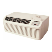
Airflow
Install
Screws
Removed
From
Back
Panel
Figure 8
Vertical Blower Assembly
5. Tighten the two screws below the duct opening that
were loosened in step 2.
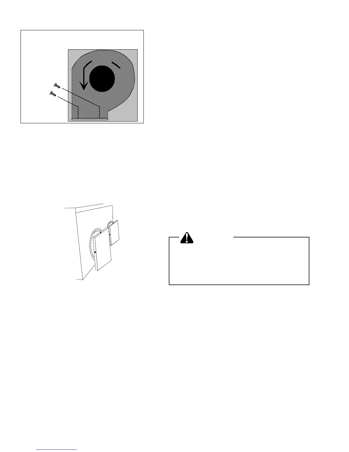
6. Use both the horizontal duct cover kit (CHK001*)
and Round to horizontal duct kit to complete the
installation. (Figure 9)
Figure 9
Horizontal Duct Cover Kit
Ductwork
Duct systems and register sizes must be properly de-
signed for the C.F.M. and external static pressure rating
of the unit. Ductwork should be designed in accordance
with the recommended methods of Air Conditioning
Contractors of America Manual D (Residential) or Manual
Q (Commercial). All ductwork exposed to the outdoors
must include a weatherproof barrier and adequate insu-
lation.
A duct system should be installed in accordance with
Standards of the National Board of Fire Underwriters for
the Installation of Air Conditioning, Warm Air Heating
and Ventilating Systems. Pamphlets No. 90A and 90B.
The warm air supply duct from the unit through a wall
fabricated of combustible material may be installed
without clearance. However, minimum clearances for
the unit must be observed as shown in Specification
Sheet.
The outlet duct should be provided with an access
panel.
For vertical airflow, the ductwork should be attached to
the roof curb prior to installing the unit. Ductwork di-
mensions are shown in the Amana PRC roof curb instal-
lation manual.
If desired, supply and return duct connections to the unit
may be made with flexible connections to reduce
possible unit operating sound transmission.
Filters
CAUTION
To prevent property damage due to fire
and loss of equipment efficiency or
equipment damage due to dust and lint
build up on internal part, never operate
unit without a filter installed .
Even though a return air filter is not supplied with this
unit, there must be a means of filtering all return air.
Refer to Specification Sheet provided with unit for filter
size information.
If using the Over/Under Transition Kit, the filter(s) may
be located in the return air duct(s) or return air filter
grille(s). Filters installed external to the unit should be
sized in accordance with their manufacturer recommen-
dations. A throwaway filter must be sized for a maxi-
mum face velocity of 300 feet per minute.
Filter Installation
Important: When installing a filter, the air flow arrows
on the filter must point toward the indoor blower.
 Loading...