Do you have a question about the Amana RHE**A2 Series and is the answer not in the manual?
Covers manual scope, unit handling, and general installation advice.
Details outdoor unit placement, minimum clearances, and rooftop installation guidelines.
Notes on indoor equipment and ductwork adequacy for proper performance.
Guidance on line sizing, routing, insulation, and protection to ensure performance.
Instructions for filter drier installation and making proper sweat connections.
Critical safety practices for handling refrigerants and performing leak tests.
Details wiring requirements, grounding, thermostat connections, and safety precautions.
Guides for preliminary and final charge adjustment, including cooling and heating operation.
Explains the two types of defrost controls and their operation.
Details operation and adjustment of time and temperature defrost controls.
Describes defrosting based on coil temperature and last defrost cycle duration.
A comprehensive checklist for verifying proper installation and operation.
Illustrates thermostat wiring for various configurations with indoor blower coils.
This document outlines the installation and maintenance procedures for Amana RHE**A2* Remote Heat Pumps, designed for heating and air conditioning applications. It emphasizes safety, proper installation techniques, and routine checks to ensure optimal performance and longevity of the unit.
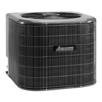
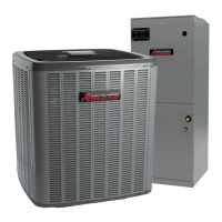
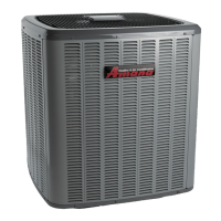
The Amana RHE**A2* Remote Heat Pump is a split-system unit designed for both heating and cooling residential and commercial spaces. It operates by transferring heat between the indoor and outdoor environments. In cooling mode, it extracts heat from the indoor air and releases it outdoors. In heating mode, it extracts heat from the outdoor air and transfers it indoors. The system utilizes R-22 refrigerant and requires careful handling and installation in accordance with EPA regulations. The outdoor unit is factory-charged with R-22, sufficient for a matching indoor blower coil or A-coil plus 25 feet of 3/8-inch liquid line, with adjustments needed for different line lengths. The system integrates with an indoor blower coil and a thermostat to regulate indoor temperature. Defrost cycles are managed by either a time and temperature-based control or a demand defrost control, ensuring efficient operation in colder climates. Electrical connections are critical for the unit's operation, requiring proper grounding and adherence to local and national electrical codes.
The heat pump offers versatile usage, providing both cooling and heating capabilities. For cooling operation, the room thermostat should be set to COOL and the fan switch to AUTO, with the temperature control set well below the room temperature. For heating, the thermostat should be set to HEAT and the fan switch to AUTO, with the temperature control set well above the room temperature. The system's performance is influenced by outdoor temperature, and specific charge adjustments are detailed for both matching and non-matching indoor coil systems. For systems with expansion valves indoors, subcooling measurements are used to adjust the refrigerant charge, aiming for 9°F to 13°F subcooling at stabilized cooling conditions and outdoor temperatures of 60°F or higher. For orifice or cap tube indoor coils, superheat measurements are used, with the target superheat varying based on outdoor temperature as indicated in a provided chart.
The unit's defrost system is crucial for maintaining heating efficiency in cold weather. Two types of defrost controls are available: time and temperature defrost control, and demand defrost control. The time and temperature control initiates defrost based on coil temperature and compressor run time, which is factory-set at 90 minutes but adjustable to 30 or 60 minutes. The demand defrost control adjusts the run time between defrost periods automatically, ranging from 30 to 360 minutes, based on coil temperature and the length of the last defrost cycle. These controls ensure that ice buildup on the outdoor coil is managed effectively, preventing performance degradation.
Electrical connections are straightforward but require careful attention to detail. The unit is designed for single-phase reciprocating compressors, and hard start components may be required, especially with indoor coils that have thermal expansion valves. The thermostat connections are critical for proper system control, with various approved thermostat models listed. The system supports different electric heat staging configurations, allowing for flexible integration with electric heaters to meet specific heating loads, as determined by Manual J or Right-J calculations.
Regular maintenance is essential for the heat pump's efficient and safe operation. The installation instructions emphasize several key maintenance-related checks and procedures. Prior to initial startup, it is crucial to connect electrical power to the unit for four hours if it has a crankcase heater, to prevent compressor damage. The refrigerant lines must be properly sized, routed, and insulated, with a filter drier installed in the liquid line as per instructions to maintain refrigerant purity and system integrity. All sweat connections must be carefully brazed, quenched, and leak-tested using dry nitrogen, never oxygen or flammable gases, to prevent explosions and ensure a leak-free system. System evacuation to 250 microns or less is critical to remove moisture and non-condensibles, which can severely impact performance and lifespan.
During troubleshooting, the first steps always involve checking for clean coils, clean filters, and proper airflow. Indoor airflow should be between 350 to 450 CFM per ton of cooling capacity. Establishing proper indoor airflow can often be done by measuring heating temperature rise. If further information is needed, the Remote Heat Pump Service Manual is recommended.
A comprehensive system checklist is provided to guide installers through critical checks before leaving the job site. This includes verifying that the condenser fan blade rotates freely, refrigerant tubing is properly supported and free from rubbing, indoor and outdoor sections are level and properly supported, and all electrical connections are tight. It also covers checking the compressor sound, indoor blower motor amperage, and ensuring all access panels are installed and secured. The checklist also includes verifying control function, voltage within tolerance, and proper air flow across the indoor coil. Finally, it ensures that the owner understands the unit's operation, thermostat usage, filter location and cleaning schedule, and knows whom to contact for service. The User's Guide must be filled out and left with the owner.
For servicing the defrost system, specific procedures are outlined to rapidly advance through a defrost cycle. This involves placing jumper wires on the defrost control board to simulate conditions that trigger a faster defrost, allowing technicians to quickly verify its functionality. After servicing, all jumper wires must be removed, and panels replaced. These detailed steps ensure that the unit remains in optimal condition and operates safely throughout its lifespan.
| SEER | Up to 16 |
|---|---|
| Refrigerant | R-410A |
| Compressor | Scroll |
| Cabinet | Galvanized Steel |
| Coil | All-Aluminum Evaporator Coil |
| Cooling Capacity (BTU/h) | 24, 000 - 60, 000 |
| Heating Capacity (BTU/h) | 24, 000 - 60, 000 |
| Warranty | 10-year limited parts warranty |