2.2.3
2.2.4
2.2.5
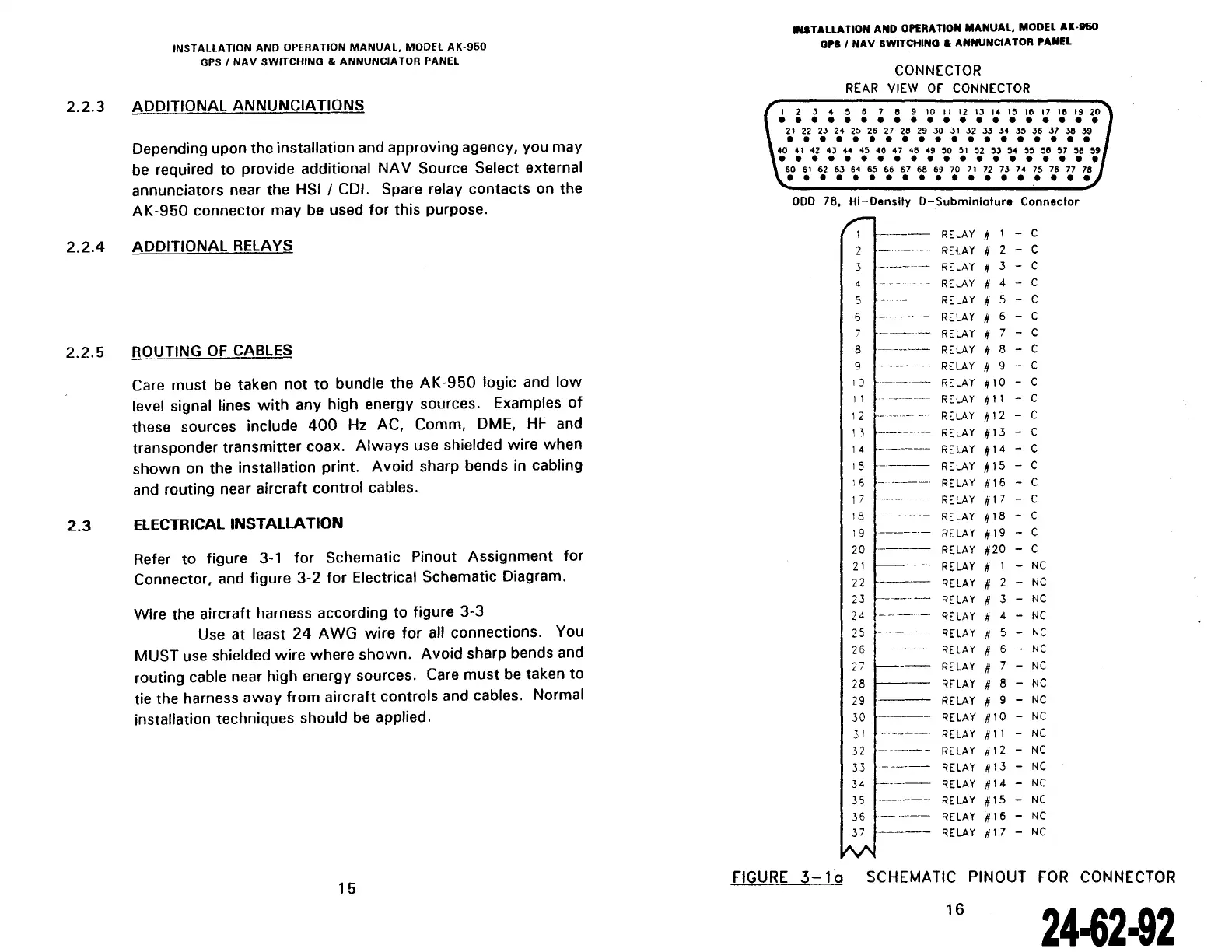
2.3
INSTALLATION
AND
OPERATION
MANUAL,
MODEL
AK-960
GPS
1
NAV
SWITCHING
&
ANNUNCIATOR
PANEL
ADDITIONAL ANNUNCIATIONS
Depending upon the installation and approving agency, you may
be required
to
provide additional
NA
V Source Select externat
annunciators near the HSI
1 CDI. Spare relay contacts on the
AK-950
connector may be used
for
this purpose.
ADDITIONAL RELAYS
ROUTING
OF
CABLES
Care must be taken
not
to
bundle the
AK-950
logic and
low
levet signal tines
with
any high energy sources. Examples
of
these sources include
400
Hz AC, Comm, DME,
HF
and
transponder
transmitter
coax.
Always
use shielded wire
when
shawn
on the installation print. A void sharp bends in cabling
and routing near aircraft
control
cables.
ELECTRICALINSTAllATION
Refer
to
figure 3-1
for
Schematic Pinout Assignment
for
Connector, and figure 3-2
for
Electrical Schematic Diagram.
Wire the aircraft harness according
to
figure
3-3
Use at least
24
AWG
wire
for
ali connections. Vou
MUST use shielded wire where
shawn.
A void sharp bends and
routing cable near high energy sources. Care
must
be taken
to
tie the harness
away
from
aircraft contrais and cables. Normal
installation techniques should be applied.
15
IN8TALLATION AND OPERATION MANUAL, MODEL
Al-160
OPS
1
NAV
SWITCHINO.
ANNUNCIATOR PANEL
CONNECTOR
REAR
VIEW
Of
CONNECTOR
1 2 J 4 5 6 7 8 9 10
Il
12
13 14 15 16 17 18
19
20
• • • • • • • • • • • • • • • • • • • •
21
22 23 24 25 26 27 26 29
30
31
32
33 34 35 36 37 36
39
• • • • • • • • • • • • • • • • • • •
40
41
42 43 H 45 46 4 7 48 49
50
51
52
53
54
55 56 57
511
59
• • • • • • • • • • • • • • • • • • • •
60
61
62
63
64
65 66 67
68 69 70
71
72 73 74 75
76
77 78
• • • • • • • • • • • • • • • • • • •
000
78,
HI-Oenslly
0-Submlnlolure
Conneclor
r:-
---
RE
LAY
RElAY
2
---
3
4
5
6
------
RELAY
--
RELAY
RE
LAY
RELAY
Il 1 - c
# 2 - c
# 3 - c
# 4 - c
# 5 - c
# 6 - c
7
----
RELAY
# 7 - C
8
------
RELAY
# 8 - C
9 - -
RELAY
/1
9 - C
10
-------
RELAY
#10-
C
Il
---------
RELAY
/111
- C
12
RELAY
#12 - C
1 3
-----
RE
LA
Y # 1 3 - C
14
-----
RELAY
/114-
C
1 5
-----
RE
LA
Y # 1 5 - C
16
-
------
RELAY
/116 - C
1 7 -
----
---
--
RE
LA
Y
/1
1 7 - C
1
8 -
RE
LA
Y # 1 8 - C
19
-------
RELAY
#19-
C
20
----
RELAY
#20
- C
21
RELAY
# 1 -
NC
22
RELAY
# 2 -
NC
23
'------
RELAY
# 3 -
NC
24
-----
RELAY
# 4 -
NC
25
----
·-·
RELAY
# 5 -
NC
26
----
RELAY
# 6 -
NC
27
----
RELAY
If
7 -
NC
28
---
RELAY
# 8 -
NC
29
RELAY
# 9 -
NC
30
RELAY
1110
-
NC
.31
RELAY
#11 -
NC
32
-------
RELAY
"12
-
NC
33
-----
RELAY
#13
-
NC
34
-----
RE
LAY
/114 -
NC
35
RELAY
/115 -
NC
36
--
----
RELAY
Il 16 -
NC
37
----
RELAY
1117
-
NC
IV\
FIGURE
3-1
a SCHEMA
TIC
PINOUT
FOR
CONNECTOR
16
24-62-92
The document reference is online, please check the correspondence between the online documentation and the printed version.