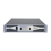
This document is a service manual for the V3001 Plus, an audio power amplifier. It provides comprehensive information for understanding, operating, and maintaining the device, covering various aspects from its internal structure to troubleshooting common issues.
The primary function of the V3001 Plus is to amplify audio signals, delivering high-power output suitable for professional audio applications. It features multiple input and output options, allowing for flexible integration into various sound systems. The device is designed to operate in different modes, including parallel, stereo, and bridge mono, providing versatility for different amplification needs. Users can select between these modes to optimize the amplifier's performance for specific speaker configurations or power requirements.
For ease of use, the V3001 Plus incorporates several control features. It includes volume controls for both front and rear channels, enabling precise adjustment of audio levels. A balance circuit is integrated to fine-tune the audio balance between channels. The amplifier also features a SUB WOOFER switch and an HPF (High-Pass Filter) switch, which allow users to tailor the frequency response for subwoofers or to filter out low frequencies, respectively. These controls contribute to a more refined and customized audio output.
The device is equipped with various indicators to provide real-time feedback on its operational status. These include Clip LEDs, Signal LEDs, and -10dB and -20dB LEDs, which help users monitor input and output levels, identify potential clipping, and ensure optimal performance. A Protect LED indicates when the amplifier is in protection mode, safeguarding it from damage due to overload or other faults. These visual cues are essential for both setup and ongoing monitoring during operation.
The V3001 Plus also includes a Limiter function, which helps prevent signal distortion and speaker damage by capping the output level. This feature is crucial for maintaining audio integrity and extending the lifespan of connected equipment, especially in high-volume scenarios. The presence of a Front/Rear switch further enhances its adaptability, allowing users to direct audio output to different speaker zones.
Maintenance and repair are well-supported by the manual's detailed diagrams and part lists. The "Exploded View" and "Exploded View Part List" provide a comprehensive breakdown of all mechanical components, facilitating assembly, disassembly, and replacement of parts. Similarly, the "Electrical Part List" and "Schematic Diagram" offer in-depth information on electronic components and circuit layouts, which are invaluable for diagnosing and repairing electrical issues. The "Printed Circuit Board Diagram" further aids in identifying components and tracing connections on the PCBs.
For troubleshooting, the manual includes a dedicated section that outlines common symptoms, possible causes, and corrective actions. This guide helps users quickly identify and resolve issues such as the device not reacting when switched on, pop noise, a dim power LED, or no sound output. This structured approach to troubleshooting empowers users to perform basic diagnostics and repairs, minimizing downtime and the need for professional service.
The internal design of the V3001 Plus features a robust power supply, including a transformer and various capacitors, to ensure stable and consistent power delivery to the amplification stages. The amplifier incorporates multiple ICs, transistors, and diodes, all working in concert to process and amplify audio signals efficiently. Cooling is managed by fans, which are essential for dissipating heat generated during operation, thereby maintaining optimal operating temperatures and preventing thermal damage.
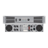
Connectivity options are extensive, including input jacks for balanced and unbalanced signals, and speakon connectors for speaker outputs. The "Point To Point Wiring Diagram" illustrates the interconnections between different PCB assemblies, such as the power supply PCB, input jack PCB, output PCB, display PCB, and amplifier PCBs. This diagram is critical for understanding the overall wiring architecture and for performing any wiring-related maintenance or repairs.
Overall, the V3001 Plus is a versatile and powerful audio amplifier designed for demanding environments. Its comprehensive manual ensures that users have all the necessary information to operate, maintain, and troubleshoot the device effectively, making it a reliable choice for professional audio applications.