EasyManua.ls Logo

American Standard 4A6V8048A1000A - User Manual

American Standard 4A6V8048A1000A
28 pages
Print Icon
To Next Page IconTo Next Page
Loading...
SSAAFFEETTYY WWAARRNNIINNGG
Only qualified personnel should install and service the equipment. The installation, starting up, and servicing of heating, ventilating, and
air-conditioning equipment can be hazardous and requires specific knowledge and training. Improperly installed, adjusted or altered
equipment by an unqualified person could result in death or serious injury. When working on the equipment, observe all precautions in the
literature and on the tags, stickers, and labels that are attached to the equipment.
October 2014
11-BC37D1-1D-EN
Variable Speed AccuLink System
Heat Pumps and Air Conditioners
4A6V8024A1000A
4A6V8036A1000A
4A6V8037A1000A
4A6V8048A1000A
4A6V8049A1000A
4A6V8060A1000A
4A7V8024A1000A
4A7V8036A1000A
4A7V8037A1000A
4A7V8048A1000A
4A7V8060A1000A
Scan to see help
videos on this
product
NNoottee:: “Graphics in this document are for representation
only. Actual model may differ in appearance.
Installers Guide
Question and Answer IconNeed help?

Do you have a question about the American Standard 4A6V8048A1000A and is the answer not in the manual?

Summary

Installers Guide Overview

General Safety Warning

Critical safety instructions for personnel installing or servicing the equipment.

Outdoor Unit Safety Precautions

Hazardous Voltage and Power Disconnection

Warning regarding hazardous voltage and the necessity of disconnecting all power before servicing.

Refrigerant Oil and Handling Safety

Guidelines for safe handling of R-410A refrigerant, oil, and system pressures.

Electrical Safety and System Compatibility

High Voltage Electrical Hazard

Warning about 400VDC electrical hazard and waiting period after power disconnection.

Refrigerant Line Brazing Procedure

Brazing Process and Heat Protection

Detailed steps for brazing, including using a wet rag for heat protection.

Refrigerant System Integrity Checks

Performing Refrigerant Line Leak Checks

Method for leak testing refrigerant lines using nitrogen and soapy solution.

Evacuating Refrigerant Lines and Indoor Coil

Procedure for evacuating the system to a specified micron level.

System Charging: Weigh-In Method

Calculating Charge for New Installations

Step-by-step guide to calculate refrigerant charge for new installations.

Calculating Charge for Sealed-System Repairs

Steps to calculate refrigerant charge for sealed-system repairs.

Service Valve Operation

Opening the Liquid Service Valve Safely

Instructions for safely opening the liquid service valve with caution.

Low Voltage Electrical Connections

High Voltage Electrical Connections

System Start-Up Procedure

System Charge Adjustment and Subcooling

Subcooling Correction Calculations

Guide to determine final subcooling using line length, lift, and correction charts.

Refrigerant Charging Data and Charts

Charging the Unit and Verifying Performance

Attaining Proper Gage Pressure

Steps to adjust refrigerant level using the charging chart for correct pressures.

Defrost Control Operation (Heat Pump Only)

Forced Defrost Procedure via CDA

Steps to initiate and manage a forced defrost cycle through the CDA.

Final Installation Checkout Procedures

Comprehensive Installation Checklist

A checklist to confirm all installation steps and requirements have been met.
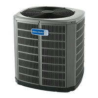
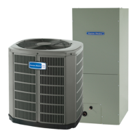
American Standard 4A6V8048A1000A Specifications

General IconGeneral
TypeSplit System Air Conditioner
Model4A6V8048A1000A
Cooling Capacity4 tons
SEER Rating16
HSPFNot Applicable
StagesSingle Stage
RefrigerantR-410A
Cooling Capacity (BTU)48, 000 BTU
Voltage208/230V
Phase1
Sound Level (Outdoor Unit)74 dB
Weight (Outdoor Unit)260 lbs

Related product manuals