18-CD24D1-2 9
Installer’s Guide
Table 1
Minimum Clearance to Combustible Materials
Upflow Closet
Left Side 0 inches Front 3 inches (note 1)
Right Side 0 inches Back 0 inches
Flue 6 inches * Top 1 inch
Horizontal Closet
(see note 2)
Top 2 inches Back 3 inches
Flue 6 inches * Sides 1 inch
Front 18 inches (note 1)
Horizontal Alcove
(see note 2)
Top 1 inch Back 0 inches
Flue 6 inches Sides 0 inches
Front 18 inches
* May be 1" when type B-1 vent is used
NOTES:
1) Minumum clearance to front on *UD2D120 is 6 inches
2) May be installed on combustible floor when type B-1 vent is used.
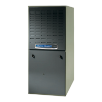
Figure 6: Bottom View - Pre-drilled holes
1
2
3
4
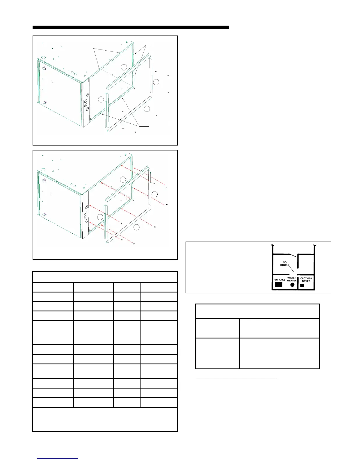
Figure 7: Bottom View -
Flange Attachment
AIR FOR COMBUSTION AND VENTILATION
Adequate flow of combustion and ventilating air must
not be obstructed from reaching the Furnace. Air open-
ings provided in the Furnace casing must be kept free
of obstructions which restrict the flow of air. Airflow re-
strictions affect the efficiency and safe operation of the
Furnace. Keep this in mind should you choose to re-
model or change the area which contains your Furnace.
Furnaces must have a free flow of air for proper perfor-
mance.
Provisions for combustion and ventilation air shall be
made in accordance with “latest edition” of Section 5.3,
Air for Combustion and Ventilation, of the National
Fuel Gas Code, ANSI Z223.1, or Sections 7.2, 7.3 or 7.4
of CSA B149.1 Installation Codes, and applicable provi-
sions of the local building codes. Special conditions cre-
ated by mechanical exhausting of air and fireplaces
must be considered to avoid unsatisfactory Furnace op-
eration.
Furnace locations may be in “confined space” or “uncon-
fined space”. Unconfined space is defined in Table 2 and
Figure 8. These spaces may have adequate air by infil-
tration to provide air for combustion, ventilation, and
dilution of flue gases. Buildings with tight construction
(for example, weather stripping, heavily insulated,
caulked, vapor barrier, etc.), may need additional air
provided as described for confined space.
TABLE 2
1. All air from inside the building as in Figure 10: The
confined space shall be provided with two perma-
nent openings communicating directly with an addi-
tional room(s) of sufficient volume so that the com-
bined volume of all spaces meets the criteria for an
unconfined space. The total input of all gas utiliza-
tion equipment installed in the combined space
shall be considered in making this determination.
Refer to Table 3, for minimum open areas required.
MINIMUM AREA IN SQUARE FEET
FOR UNCONFINED SPACE INSTALLATIONS
FURNACE
MAXIMUM BTUH
INPUT RATING
WITH 8 FT. CEILING
MINIMUM AREA IN SQUARE
FEET OF UNCONFINED SPACE
60,000
80,000
100,000
120,000
140,000
375
500
625
750
875
50 CU. FT. OR MORE
PER 1000 BTU/ HR. INPUT
ALL EQUIP. INSTALLED
UNCONFINED
Figure 8
Use pre-drilled
holes
Use pre-
drilled
holes
1
2
3
4
Use pre-
drilled
holes
 Loading...