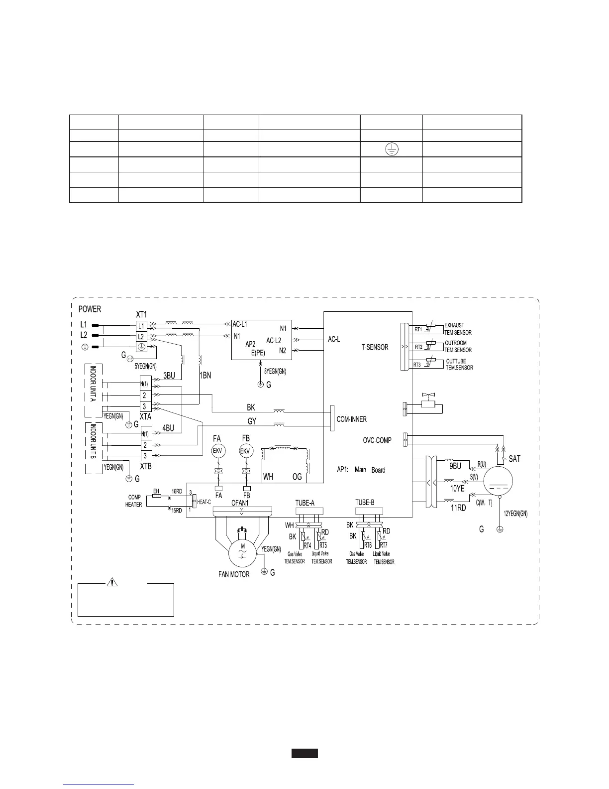
Wiring Diagrams
Symbol Symbol Color Symbol Symbol Color Symbol Name
WH White GN Green COMP Compressor
eriw gniduorGnworBNBwolleYEY
RD Red BU Blue
YE/GN Yellow/Green BK Black
VT Violet OG Orange
n
Color Key
NOTE: The wiring diagrams in this guide are included as a reference. The manufacturer
has a policy of continuous product and product data improvement and reserves the
right to change design and specifications without notice. Always check the unit
nameplate and wiring diagram for the actual unit requirements.
Wiring Diagram 18K
COMP.
4YV
than 30V to prevent the risk of electrical shock!
of terminal P(DC+) and N(DC-) at AP1 is higher
Please don't touch any terminal when the voltage
WARNING
L1
6BN
7BU
L2
L2
2BN
N1
N2
4V
U
V
W
RD
BU
YE
L4
L4
L4
X1
14WH
13WH
5
BK
WH
LX1-1 LX1-2
WH
RD
BU
BN
BK
C1
BU
BN
BU
L
L3
5
5
5
L5
L6
L7
L7
YE
Note: A "Jumper Cap" may be used to determine fan speed and the swing angle of horizontal louver
for this model. The unit will not operate without the correct jumper cap. If "Jumper Caps" are installed
on the original electrical board, they must be removed and installed on a replacement electrical
board.
30