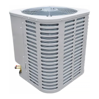
Do you have a question about the Ameristar M4AC6 and is the answer not in the manual?
Warning about hazards of working with live electrical components during service.
Warning regarding use by persons with reduced capabilities and need for supervision.
Warning to ensure children do not play with the appliance.
Caution to ensure existing refrigerant lines are brazed, not soldered.
Caution about hot compressor domes and potential for burns.
Table detailing physical dimensions and estimated weight for M4AC6 models.
Specifies maximum total length and vertical change for refrigerant lines.
Guidance on positioning the outdoor unit for optimal performance and airflow.
Recommendations for installations near salt water environments.
Steps for inspecting the unit for damage and removing it from the pallet.
Guidelines for installing the support pad for the outdoor unit.
Table detailing refrigerant line and service valve connection sizes for models.
Information about factory charge and verifying system charge.
Instructions to determine and record required refrigerant line length and lift.
Importance of insulating the vapor line and preventing contact between lines.
Precautions for reusing existing refrigerant lines in retrofit applications.
Recommendations to prevent noise from vibration and proper line routing techniques.
Step-by-step instructions for preparing and brazing refrigerant lines.
Procedure for pressurizing lines with nitrogen and checking for leaks.
Steps for evacuating the system to a specific micron level.
Procedure for opening the gas service valve.
Procedure and warning for opening the liquid service valve.
Table defining maximum lengths for low voltage wiring based on wire gauge.
Diagrams illustrating low voltage wiring connections for various configurations.
Warning and guidelines for high voltage power supply connections.
Requirement to install a separate disconnect switch for high voltage.
Procedure for grounding the outdoor unit according to code.
Steps to initiate the system startup sequence after installation.
Guidance on measuring outdoor and indoor temperatures for system charging.
Detailed procedure for subcooling method of refrigerant charging in cooling mode.
Method for charging refrigerant by weight for initial installation or when subcooling is not feasible.
Final checks and operational procedures to ensure proper system performance.
A system fault chart to diagnose common issues across different operating modes.
Refrigeration circuit diagram for 6018 and 6024 models.
Refrigeration circuit diagram for 6030 and 6036 models.
Refrigeration circuit diagram for the 6042 model.
Refrigeration circuit diagram for the 6048 model.
| Brand | Ameristar |
|---|---|
| Model | M4AC6 |
| Category | Air Conditioner |
| Language | English |

 Loading...