1
Upgrade Kit AL811 and AL811H amplifier
Rev2 Aug 15, 2022
Information in this modification manual is copyright 2022 by W8JI and CTR Engineering. I understand people like to
share things, but please remember we have several weeks’ labor composing this document. Please consider a
PayPal gift to w8ji@w8ji.com when using these instructions if you do your own kit.
Please be aware MFJ has made multiple changes in the AL811 series, not all of them are good. The following are
known problems as of this date:
1.) The Cooltron fan has about 1/3 necessary airflow for (4) 811tubes in normal SSB/CW use. If your amplifier has a
Cooltron fan, you must change it. We offer a fan kit.
2.) MFJ has changed output coax grounding in later amplifiers. The coax shield grounds to the input board. This
must be corrected or amplifier stability is compromised.
Thank you for purchasing this kit (and/or modification manual). These kits and this technical manual are intended
to help fellow Hams understand failures and reduce expensive damage. This technical instruction manual and kits
bring 811 series amplifiers up to latest revisions. With basic hand tools and soldering skills anyone should be able
to upgrade or service their own amplifier.
Please order via email links on https://www.ctrengineeringinc.com/ameritron-811-811h-upgrade-
kits/ or email order query only to orders@ctrengineeringinc.com
This modification manual is also the result of feedback, questions, and suggestions by fellow Hams. More
suggestions are always welcome. The overriding philosophy is everything reasonably possible should be done to
prevent expensive or annoying damage, especially to expensive radios. An amplifier should work as well as
possible for the cost.
These kits come in two basic forms with one add-on:
(Power Supply rebuild) 811KS
1.) four better sized higher-voltage much longer-life 5000 hours 105c rated electrolytics
2.) four improved bleeder/equalizer resistors
3.) one large 6A grid meter protection diode
4.) four 499K 1% 1kV rated two-watt temperature stable meter multiplier resistors. (Note: from parts supplier
issues, we may substitute two 1M ohm resistors. The value is printed on the resistors.)
(Protection Kit) 811KP
1.) three application tested GDT tubes (one can be a spare, primary protection is at the sockets)
2.) one large 6A meter protection diode
3.) one 100k 2-watt resistor (standby noise)
4.) two 3.9V 5-watt Zener diodes (bias)
5.) 10-ohm 9-watt CCS 10kV rated fault resistor (arc limiting)
Add on part:
811R200K
200-ohm 25-watt non-inductive TO-220 case load resistor kit with hardware (reduce gain and add stability in 3
tube 811 models). This also can make the AL811H more compatible with 100W radios, reducing power overshoot
in rigs like the ICOM 7300.
Overview
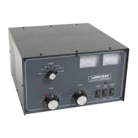
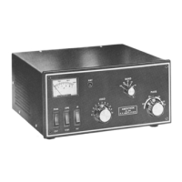
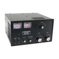
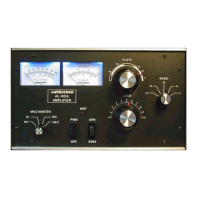
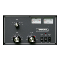
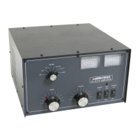
I designed the AL811 series many years ago. It was intended to be a minimal cost reasonable power level SSB and
CW only amplifier. The initial design request was for just two tubes, but that obviously would have been
inadequate. As a result, I added a third tube as a bare minimum cost amplifier, and pushed to have a better but
still not too expensive four-tube amplifier. The better version became the AL811H.


 Loading...