17
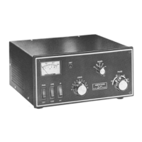
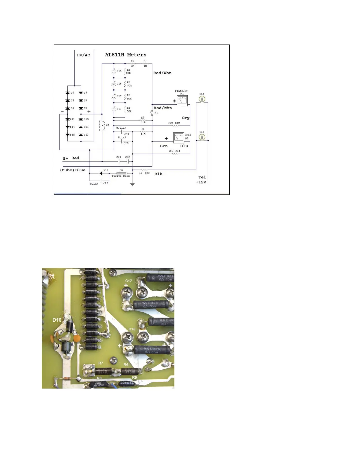
Figure 24 Metering and power supply
D16 can be mounted any physical way you like so long as the diode anode is at the center pad
and the striped cathode end is toward the rectifier bank and filter capacitor bank negative. This
diode allows the any arc energy to get from the chassis to the capacitor bank negative,
harmlessly bypassing meters. There is plenty of room to solder. The large rectifier diode in this
kit replaces D16. D16 is located near the tank coil. The kit diode has thick leads. It can lay-solder
on top of the board. It does not need to fit through holes. Refer to Figures 25 and 26.
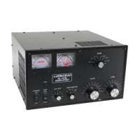
Figure 25 Meter and HV Component Locations
 Loading...