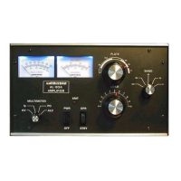
4
This kit does the following:
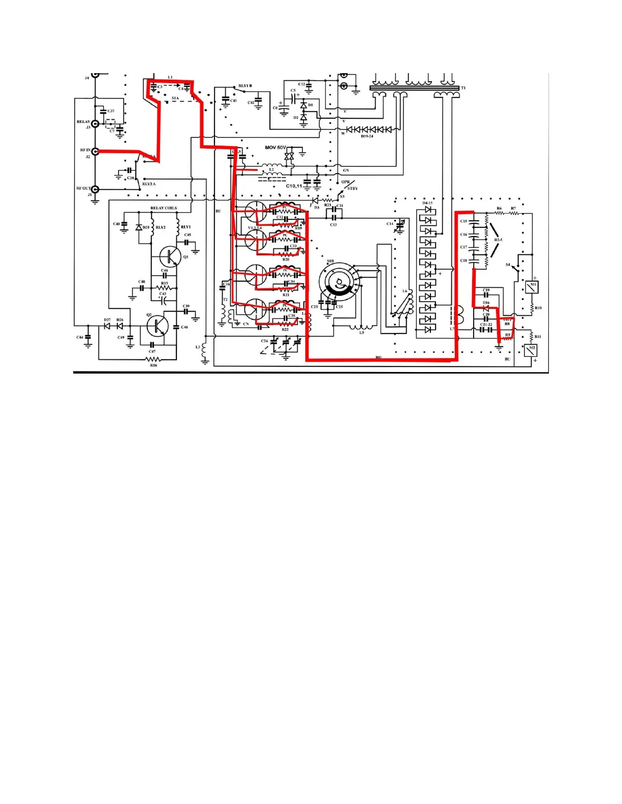
1.) Adds two “150 volt” Gas Discharge Tubes from filament directly to chassis at the tubes. These parts limit
transients to about 200 volts absolute peak. Any substitute GDT’s should be vetted for performance.
GDT’s do not clamp. GDT’s ionize at a certain voltage, becoming a near-short once ionized. This effectively
stops surges from reaching your radio if a tube should arc
2.) Instructs you to directly ground grids in older version that had grid equalizing resistors. This is a critical
update! Grid pins should always be directly grounded. THIS IS A MUST DO in any grounded grid amplifier
that floats grids from chassis.
3.) Increases or adds bias. Bias improves tube life and efficiency without noticeably hurting IMD with 3.9-volt
5-watt Zener bias diodes. If your amplifier has a string of bias diodes, found on the lower edge of the back
panel circuit board, you add only ONE of these diodes in series with the white center tap. If your amplifier
does not have a string of1N5408 bias diodes on the input board, both Zener diodes are used. The goal is
to be around 10-20mA quiescent current per tube. This would be 30-60mA zero signal keyed idle current
in the AL811, and 40-80mA idle in the AL811H