Maintenance
| 5-7
is displayed. If there is a problem storing values during parameter value
en-tering, write error Er02 is displayed. Only the Analog Range param-
eter entry does not give a display feedback when it is stored correctly. For
either error, power-down and reenter the parameters as directed in the
procedures on pages 5-7 and 5-8.
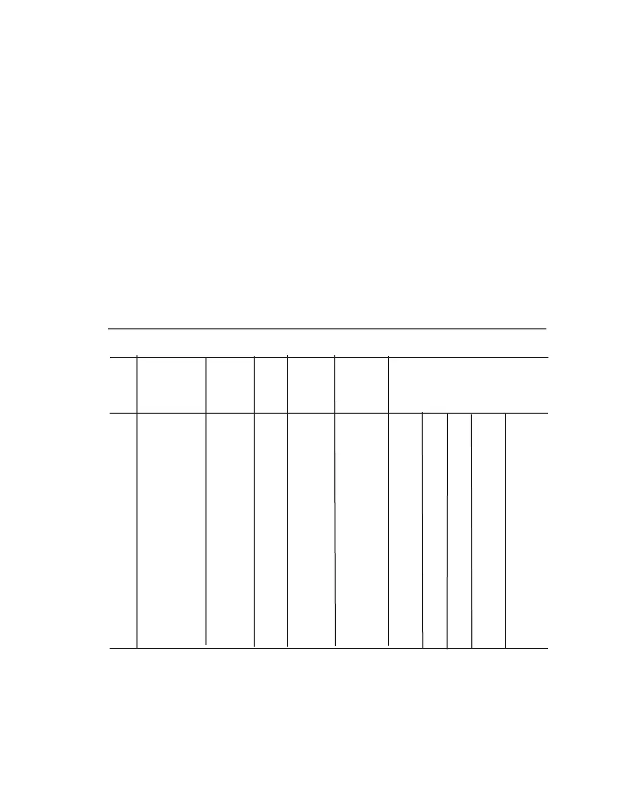
Display and LED Test
On power-up, all LED’s and display segments sequence through the set
pattern shown in the following chart at a half-second-per-step rate. The
LED’s will flash ON and OFF at about a four-per-second rate.
Observing the sequence closely lets you see if any LED or segment is not
working. Although the POWER and AC POWER LED’s are not part of the
sequence, they will be ON whenever the monitor is connected to an ac
supply and the unit is powered up.
Flashing LED Positions
STEP DISPLAY CELL ELEC STAND ALARM ANALOG RANGE
TEST TEST BY Bottom to Top
1 8.8.8.8 ON ON ON ON ON ONON ON
2 0 0 0 0 ON
3 1 1 1 1 ON ON
4 2 2 2 2 ON ON ON
5 3 3 3 3 ON ON ON ON
6 4 4 4 4 ON ON ON ON ON
7 5 5 5 5 ON ON ON ON ON ON
8 6 6 6 6 ON ON ON ON ON ON ON
9 7 7 7 7 ON ON ON ON ON ONON ON
10 8 8 8 8 ON ON ON ON ON ONON ON
11 9 9 9 9 ON ON ON ON ON ON ONON
12 P x.xx ON ON ON ON ON ONON ON

 Loading...


