EasyManua.ls Logo

Ametek JOFRA ATC-125 A - User Manual

Ametek JOFRA ATC-125 A
124 pages
Print Icon
To Next Page IconTo Next Page
Loading...
Reference Manual
Temperature Calibrator
JOFRA ATC-125/140/156/157/250/320/650 A/B
Copyright 2009 AMETEK Denmark A/S

Table of Contents

Other manuals for Ametek JOFRA ATC-125 A

Questions and Answers

  • J
    julie16Aug 20, 2025
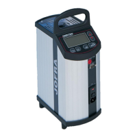
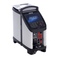
    How to fix no light in display error in Ametek JOFRA ATC-125 A Measuring Instruments?
    • K
      Karen TaylorAug 20, 2025
      If the Ametek Measuring Instruments display shows no light, begin by inspecting the fuses in the mains inlet. Then, check the fuses located on the Power PCB: F1 – F6 for ATC-125, F1 – F7 for ATC-140/155/156/157, and F1 – F7 for ATC-250/320/650. Also, check the supplies and replace the Power PCB if necessary, as a defective regulator on the Power PCB could be the cause.
  • L
    lewiskatieAug 22, 2025
    What to do if stirring motor is not pulling stirring magnet in Ametek Measuring Instruments ATC-140/250 A/B?
    • S
      Sarah HernandezAug 22, 2025
      To resolve the issue of the stirring motor not pulling the stirring magnet in Ametek Measuring Instruments ATC-140/250 A/B, set the stirring speed to 50. Measure the voltage across CN11 on the ATC-250 and CN13 on the ATC-140; it should be approximately 18V. If the voltage is correct, replace the motor. If there's no signal, check for a 5V signal on (ATC-140 Power PCB CN9 pin 11) or (ATC-250 Power PCB CN3 pin 11). If the 5V signal is present, replace the Power PCB; otherwise, inspect the ribbon cable and Main PCB. Also, if the stirring magnet has a flat side due to wear, replace it.
  • J
    Jennifer HallAug 30, 2025
    What should I do if my Ametek JOFRA ATC-125 A ATC-155 isn't cooling or heating enough?
    • L
      Leon HoganAug 30, 2025
      To address the issue of the calibrator not cooling or heating sufficiently (ATC-155 only) on Ametek Measuring Instruments, set the temperature to –50°C. On the power PCB, measure the voltage between CN8 terminal 1(+) and terminal 2(-) and the voltage between CN1 terminal 1(+) and terminal 2(-). If the voltage on CN1 is higher than 30V, replace the well and recalibrate the unit. If the voltage on CN8 is 0.45V ±0.01V and the calibrator does not cool down sufficiently, replace the well and recalibrate the unit. If the voltage on CN1 is less than 30V and the voltage on CN8 differs from 0.45V ±0.01V, adjust R9 until the voltage is 0.45V ±0.01V. If it is impossible to adjust the voltage on CN8, replace the Power PCB.
  • D
    Derrick MorrowSep 1, 2025
    What causes no readout in display error in Ametek JOFRA ATC-125 A?
    • C
      Cassandra DuncanSep 1, 2025
      If the Ametek Measuring Instruments display shows no readout, check the ribbon cable between the Main PCB and the display PCB. Also, check the ribbon cable between the display PCB and the display module, as the communication between the CPU and the display may be defective.
  • V
    Veronica LawsonSep 6, 2025
    Why are keys not functioning on my Ametek Measuring Instruments?
    • J
      Joseph ScottSep 6, 2025
      If one or more keys are not functioning on your Ametek Measuring Instruments, check the cable connection between the keyboard and the display PCB. Also, check all keys in the Service Menu, as the connection to the Main PCB may be defective.
  • M
    mtaylorSep 9, 2025
    How to fix 'Calibrator type illegal' error on Ametek Measuring Instruments?
    • S
      Seth YoungSep 9, 2025
      To resolve the "Calibrator type illegal" error message on your Ametek Measuring Instruments, check that the calibrator setting is correct on the Main PCB. Refer to section 2.3.1 in the manual for DIP Switch Setting instructions.
  • C
    Christopher VegaSep 12, 2025
    What to do when Ametek JOFRA ATC-125 A shows 'AD-converter not responding' error?
    • T
      Tammy ReedSep 12, 2025
      To address the "AD-converter not responding" error message on your Ametek Measuring Instruments, first, verify that all voltages on the power PCB are correct. If they are correct, the Main PCB is likely defective and should be replaced. If the voltages are incorrect, replace the Power PCB.
  • M
    Misty PriceSep 14, 2025
    How to resolve 'Slave temperature too high' error on Ametek JOFRA ATC-125 A Measuring Instruments?
    • A
      Amber RodriguezSep 14, 2025
      To address the "Slave temperature too high" error message on your Ametek Measuring Instruments, after the main adjustment has stabilized, check the measuring circuit by creating a short circuit in the differential TC connection (CN16 on the input board) instead of the sensors. Then, in the Service Input Menu, verify that the Slave TC reads 0°C±0.1°C. If it reads correctly, the issue lies with the sensor. Otherwise, the Main PCB is faulty.
  • S
    Steven FoxNov 16, 2025
    How to troubleshoot calibrator not heating issues in Ametek JOFRA ATC-125 A Measuring Instruments (ATC-250/320/650)?
    • J
      Jennifer JuarezNov 16, 2025
      To address the issue of the calibrator not heating on the ATC-250/320/650 models, first, check the impedance of the heating elements. The main elements should measure approximately 29 Ohms +10% - 5% each, and the top elements should measure around 96 Ohms +10% - 5% each. For ATC-250, the main should be 60 Ohms ±10% and top 200 Ohms ±10%. Then, power on the instrument and set the temperature to the maximum (250°C for ATC-250, 320°C for ATC-320, or 650°C for ATC-650). Verify that relay K1 is engaged. If the relay isn't engaged, create a short circuit in connector CN4. If this engages the relay, the sensor is likely defective; replace it if possible, otherwise, replace the entire well, then adjust and calibrate the unit. If short circuit does not engage the relay, the Power PCB is defective. ...
  • M
    Malik MaynardNov 24, 2025
    How to troubleshoot calibrator cooling/heating issues on Ametek JOFRA ATC-125 A Measuring Instruments (ATC-125)?
    • B
      brendaburnsNov 24, 2025
      To address the issue of the calibrator not cooling or heating sufficiently (or being slower than specified) on the ATC-125 Ametek Measuring Instruments, set the calibrator to –90°C and check the voltages on the test pins. Ensure the voltage between GND and 24V is greater than 23V. The voltage between GND and TC_Well should be 1,4V+(6.20 mV/°C x T). The voltage between GND and PWM should be between >1V and 4,5V. If the voltage between test pin 24V and GND is less than 23V at 125°C, pull out CN103 and re-measure; if still too low, check fuse F3 on the Power PCB, otherwise replace the Power PCB. If pulling out CN103 re-establishes the 24V, the Stirling Controller PCB is defect. If “Safe” is low, check “TC_Well” or “TC_SMH”, and if defective, replace the sensor. If the PWM signal is missing, t...

Ametek JOFRA ATC-125 A Specifications

General IconGeneral
Temperature Range-25 to 125°C
Stability±0.05°C
Well Diameter25 mm
DisplayLCD
Display Resolution0.01°C
Power Supply115 VAC or 230 VAC (selectable)
Dimensions63 x 172 x 260 mm (2.5 x 6.8 x 10.2 in)
Resolution0.01°C
TypeDry-block Temperature Calibrator

Related product manuals