M O D E L 2 0 5
O P E R A T O R ’ S M A N U A L
16
1616
16
3.6 MODEL 205 TO EXEL ROTOR DRIVER HOOK UP
Always turn the power supply off before making any cable or connection
changes to the power supply.
The EXEL rotor driver (Model RDR-005) connects directly to the Model 205. The rotor
driver has NO connections to the M205-CW Cooling Unit.
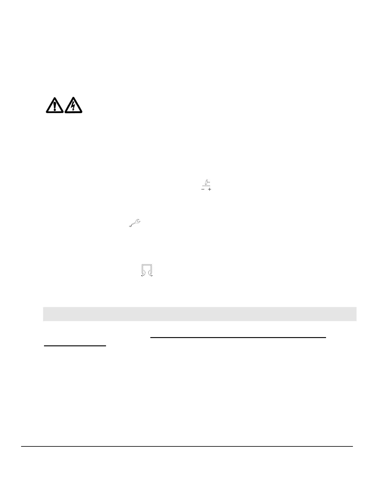
1. Attach the ground and electrode connectors on the rotor driver to their respective
GROUND(+) and ELECTRODE(-) terminals
on the Model 205. Align the
keyways, push in and turn clockwise until fully locked.
2. Attach the weldhead control male connector on the rotor driver to the WELDHEAD
CONTROL connector
on the Model 205. Note the positioning keyway and
NEVER FORCE or use tools on the cable connectors. Hand-tighten the connecting
ring being careful not to cross-thread the ring.
3. Insert the male gas quick-disconnect fitting on the rotor driver to the mating ARC
GAS OUTPUT connector on the Model 205 and hand-tighten the lock screw to
prevent accidental disconnection. Slide the rubber boot over the connection.
Note
Note: for installation of the other components of the EXEL weldhead assembly
(rotor unit and fixture) see the Exel Welding System Rotor Units and Rotor Driver
Operation Manual, P/N 740111.