AMI Analyzer Manual •
••
• 6
Installation and Operation
Receiving the analyzer
Precaution
When you receive the instrument, check the package for evidence of damage and if any is found, contact
the shipper.
Installation
Location:
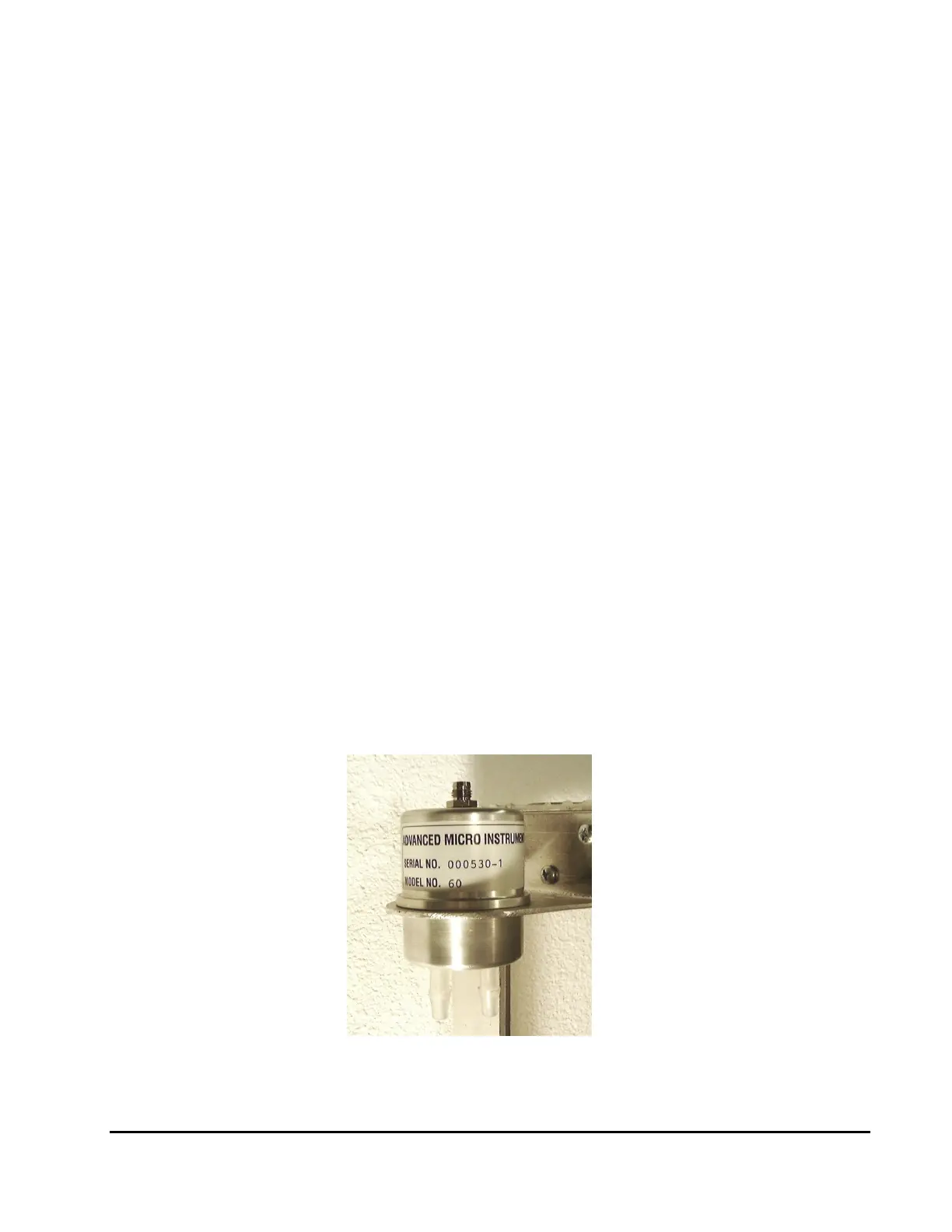
Install the probe with the electrical connection pointing upwards and the gas connections downwards in a
suitable bracket.
Mount the display unit (if used) in a suitable panel opening with 8-32 (or equivalent) screws. This unit
should be within about 6 feet of the probe.
Connect the cable provided to the probe and to the display unit, or suitable power supply (12-24V DC)
and monitoring system.
If the display unit is used, connect it to a suitable power supply (12 –24V DC), and connect the output if
desired to a suitable monitoring system.
Figure 1. Probe showing preferred mounting