EasyManuals Logo

Ampac LoopSense MAN 1572-4 Installation And Commissioning Guide

Ampac LoopSense MAN 1572-4
54 pages
To Next Page IconTo Next Page
To Previous Page IconTo Previous Page
Page #30 background imageLoading...
Page #30 background image
Page 26
LOOPSENSE EN54
INSTALLATION & COMMISSIONING
U4
CN4
CN5
CN2
CN1
CN5
CH4
RL8
RL7
RL6
RL5
RL4
RL3
RL2
RL1
ZD2
ZD1
X1
U5
U3
U2
U1
TB8
TB7
TB6
TB5
TB9
TB4
TB3
TB2
TB1
RN3
RN2
RN1
R5
R4
R2
R1
Q4
L2
L1
LK1
HY1
D3
D1
C14
C12
C11
C10
C9
C8
C7
C6
C5
C4
C2
C1
U6
M4
M2
C3
C13
SW1
C15
C16
C17
D2
M1
M5
M6
M7
M8
M9
M10
M11
M12
M13
M14
M15
M16
M17
M18
M19
R3
R6
TB10
TH1
TH2
TH4
TH3
0V
0V
+27VDC
+27VDC
EXTERNAL POWER
rev.1
EC3AW
A
B
COM
LK1 = EOL TERMINATION
///
NO NC
C
///
NO NC
CC
NCNO
///
C
NCNO
///
///
NO NC
C
C
NCNO
///
///
NO NC
C
///
NO NC
C
O/P 8
N/C
COMN/0
O/P 7
N/C
COMN/0
O/P 6
N/C
COMN/0
O/P 5
N/C
COMN/0
O/P 4
N/C
COMN/0
O/P 3
N/C
COMN/0
O/P 2
N/C
COMN/0
O/P 1
N/C
COMN/0
TB1-TB8
A
B
COM
COMMS IN / OUT
ADDRESS SW
POWER
0V
To TB1 on the Main Board
In Out
27V
1 2 3 4
ON
+27V
N/O = Normally Open, N/C = Normally Closed, C = Common
Figure 13: Remote 8 Way Relay Board PCB Layout
Relay Connections
Function
N/O = Normally Open,
C = Common
N/C = Normally Closed
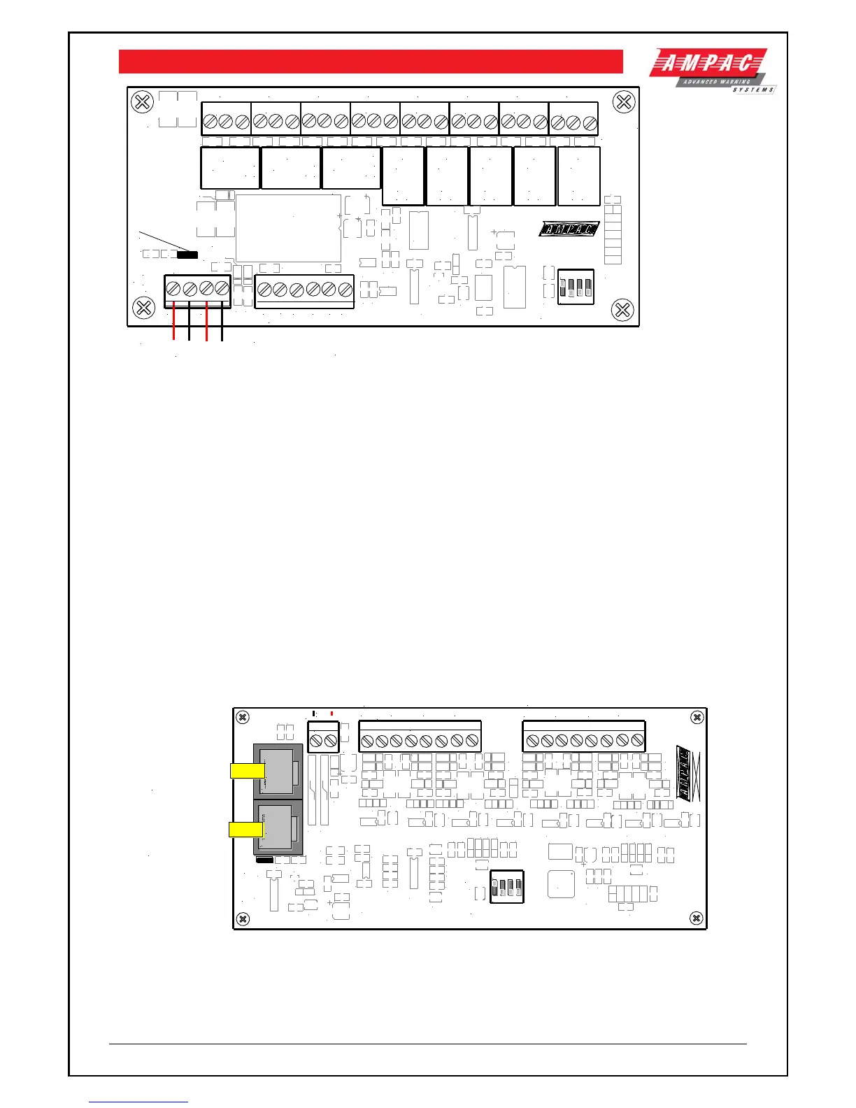
10.2 8-Way Sounder Board
The Sounder Board expands the number of sounders that can be used on an FACP by 8. Each
output is of a solid state design, rated at 24VDC / 750mA and requires a 10K End of Line (EOL)
resistor regardless of whether or not a sounder is wired to the circuit.
The sounder board is only available in a local version hence can not be mounted remotely from the
FACP.
The sounder board will switch ON the sounders as configured (output off, continuous or pulsed) at
the FACP and supervise the sounders for their open circuit, short circuit & line fault conditions.
Note: Sounder polarity MUST be observed.
U3
L1
U1
U11
C37
X1
U12
U10
U9
U8
U7
U6
U5
U4
U2
TH2TH1
TB3
TB2
TB1
SW1
RN2
RN1
R27
R26
R25
R24
R23
R21
R20
R19
R18
R17
R16
R15
R13
R12
R11
R10
R9
R8
R7
R6
R5
R4
R3
R2
R1
Q9
M17
L2
LK1
D11
D10
D8
D7
D6
D5
D4
D3
D2
D1
CN5
C47
C46
C45
C44
C43
C42
C41
C40
C39
C38
C35
C34
C33
C32
C31
C30
C29
C28
C27
C26
C25
C24
C23
C22
C21
C20
C19
C18
C17
C16
C15
C14
C12
C10
C9
C8
C7
C6
C5
C4
C3
C2
C1
R28
R29
R30
D9
RN3
U13
C13
C36
C48
C49
C50
D12
D13
D14
D15
D16
D17
D18
D19
D20
D21
D22
D23
D24
D25
D26
D27
D28
D29
D30
D31
D32
D33
D34
D35
RN4
RN5
RN6
RN7
RN8
RN9
RN10
RN11
RN12
RN13
RN14
ZD1
ZD2
ZD3
ZD4
ZD5
ZD6
ZD7
ZD8
ZD9
ZD10
ZD11
ZD12
ZD13
ZD14
ZD15
ZD16
R22
R14
C11
-VE
+VE
SOUNDER 1
-VE+VE
SOUNDER 2
-VE
+VE
SOUNDER 3
-VE
+VE
SOUNDER 4
-VE+VE
SOUNDER 5
-VE+VE
SOUNDER 6
-VE
+VE
SOUNDER 7
-VE
+VE
SOUNDER 8
DC IN
0V
27V
302-7720
EOL TERMINATION
ADDRESS SW
POWER
CN2
CN1
27V IN
- +
To Sounders 1 to 4 + / -
To Sounders 5 to 8 + / -
:
:
:
:
:
:
:
:
:
:
:
:
:
:
:
:
:
:
:
:
RS485 Control
In From Main
Board or CN2 of
Previous Board
RS485 Control
Out to Next
Board or Link 1
EOL is Applied
1 2 3 4
ON
Figure 14: 8 Way Sounder Board
Maximum Current per Output: 750mA.
Hardware

Table of Contents

Other manuals for Ampac LoopSense MAN 1572-4

Questions and Answers:

Question and Answer IconNeed help?

Do you have a question about the Ampac LoopSense MAN 1572-4 and is the answer not in the manual?

Ampac LoopSense MAN 1572-4 Specifications

General IconGeneral
BrandAmpac
ModelLoopSense MAN 1572-4
CategoryControl Panel
LanguageEnglish

Related product manuals