USB232U/485Ui
Page 10
3 MAKING THE CONNECTIONS
This chapter describes the signal and control connections that the user must make between the
USB232U/485Ui interfaces and any external serial communications devices.
3.1 External Connections
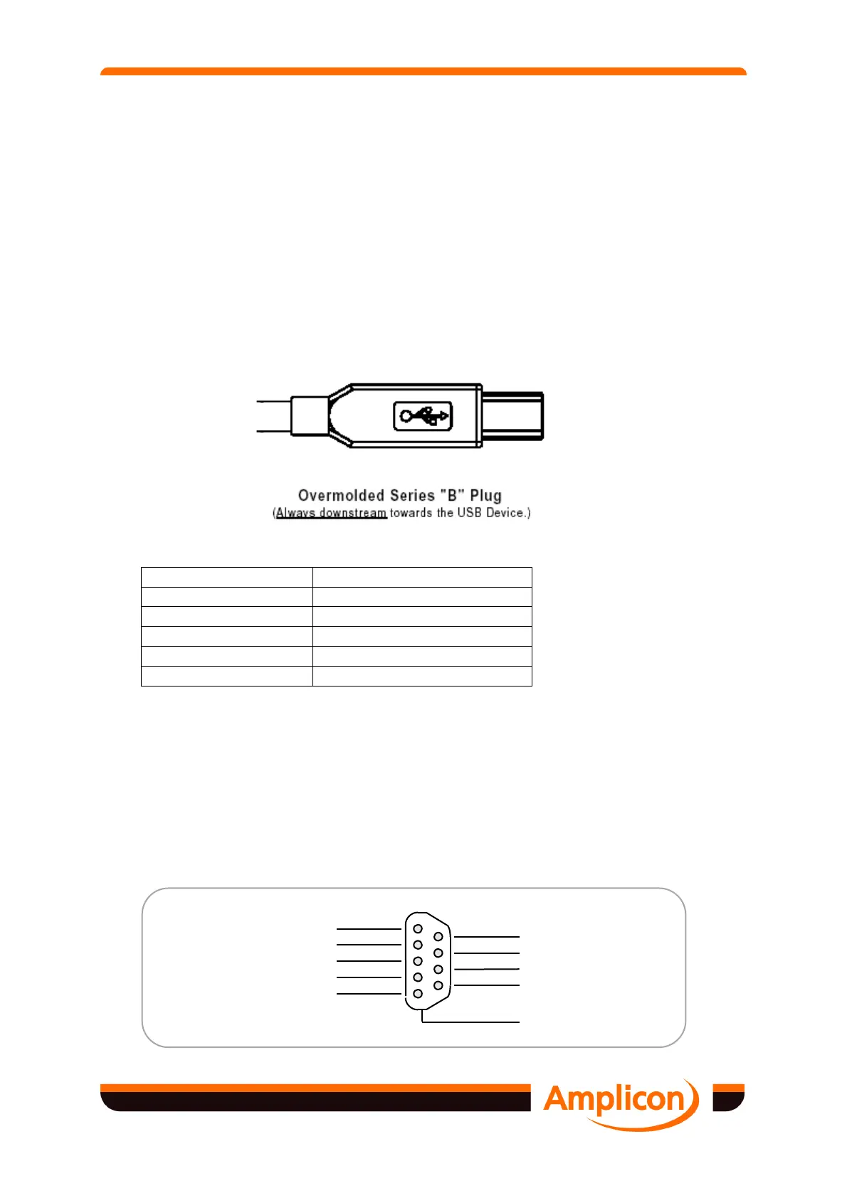
3.1.1 USB Connector
Connection to the USB port is made using a standard type B cable.
Contact Number Signal Name
1
VBUS
2
D-
3
D+
4
GND
Shell
Shield Drain Wire
Figure 3.1 USB Connector Termination Assignment
3.1.2 RS232 9-way Port
Connections to the RS232 are made via 9-way D-type connectors on the interface. The on-
board connectors are male and the mating sockets are available as accessories. Provision is
made for securing by screw jacks.
The 9-way D-type connector pin-out conforms to the industry standard and will support
commercially available cables and adapters.
5
9
4
8
3
7
2
6
1
Ring Indicator (RI)
Clear To Send (CTS)
Request To Send (RTS)
Data Set Ready (DSR)
Reference Signal Ground (SG)
Data Terminal Ready (DTR)
Transmitted Data (TXD)
Data Carrier Detect (DCD)
Received Data (RXD)
PC Chassis Ground