USB232U/485Ui
Page 17
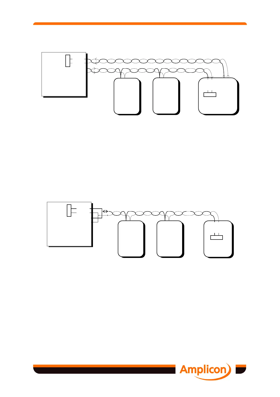
Figure 4.2 RS422 Connected in Broadcast Mode
RS485 allows multiple (up to 32) unit loads to be connected in half duplex on a single twisted
wire pair for 'party line' type of communications as illustrated in Figure 4.3. A software method
must be used to stop more than one transmitter being on the line at any time. The circuit
design is such that no damage will be done to the transceivers if several transmitters are
turned on together.
See 5.2, ‘Half Duplex Transmission Turnaround’ for a discussion of the programming required
for controlling the transmission direction.
Figure 4.3 RS485 Connected in Multi-Drop, Half Duplex Mode
4.2.3.4 RS422/485 Bus Termination
For proper operation of the RS422/485 bus in full or half duplex, multi-drop or point to point
communication, it is recommended that termination be applied to the receiver end of the data
and control lines.
The simplest form of termination is line to line with typically a 120 Ω across the differential
input, and this terminator is available on the USB485Ui interfaces, selectable by jumper JP1.
Terminator
Device n
Device 2
Device 1
A B
Tx
A' B'
Rx
A' B'
Rx
Terminator
Rx Resistor
USB485Ui
Rx - A
Rx - B
Tx - A
Tx - B
A' B'
Rx
Terminator
Rx Resistor
Device n
Device 2
Device 1
A B
Tx/Rx
A B
Tx/Rx
Terminator
Rx Resistor
USB485Ui
Rx - A'
Rx - B'
Tx - A
Tx - B
A B
Tx/Rx