USB232U/485Ui
Page 16
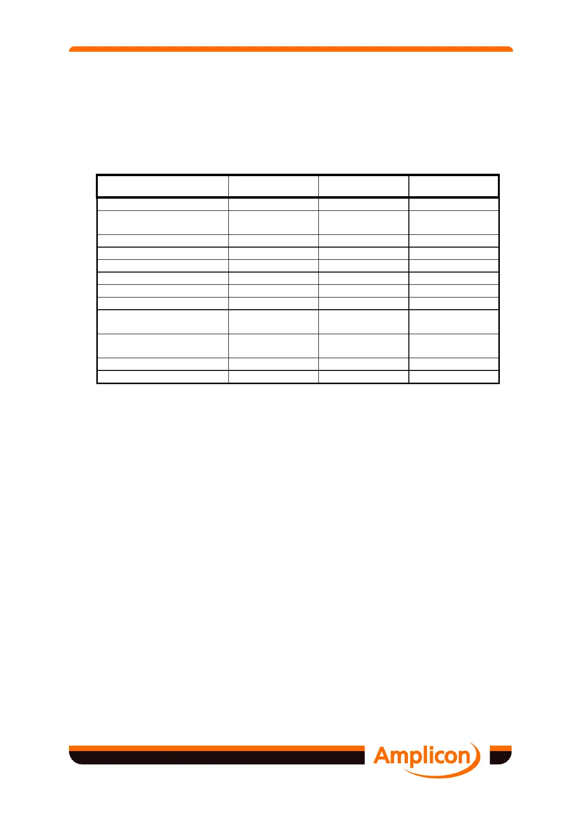
4.2.3.1 RS422/485 Parameters
The following table summarises the principal parameters of the RS422B and RS485 standards,
and shows RS232E for comparison. The actual driver/receiver devices used in the USB485Ui
Series at least meet these specifications, and provide superior performance in some cases.
EIA STANDARD RS232E RS422B RS485
Mode of Operation
Single ended Differential Differential
Number of Drivers and
Receivers on line
1 Driver
1 Receiver
1 Driver
10 Receivers
32 Drivers
32 Receivers
Max. Cable Length
15 m 1200 m 1200 m
Max. Data Rate
20 kBd 10 MBd 10 MBd
Max. Common Mode
N/A +7 V, –7 V +12 V, –7 V
Driver Voltage
±5 V to ±15 V ±2 V min ±1.5 V min
Driver Load
3 kΩ to 7 kΩ 100 Ω min 60 Ω min
Driver Slew rate
30 V/µs N/A N/A
Driver Output
Short Circuit Limit
500 mA to
Vcc or Ground
150 mA to
Ground
150 mA to Gnd
250 mA to Vcc
Receiver Input
Resistance
3 kΩ to 7 kΩ 4 kΩ 12 kΩ
Receiver Sensitivity
±3 V ±200 mV ±200 mV
Receiver Hysteresis
1.15 V 50 mV 50 mV
Figure 4.1 Communications Standards Summary
4.2.3.2 RS422/485 Signalling Sense
The RS422 and RS485 standards define the polarity of the signalling lines as follows.
"The signaling sense of the voltages appearing across the interconnecting cable is defined as
follows:
a. The A terminal of the generator shall be negative with respect to the B terminal for a
binary 1 (MARK or OFF) state
b. The A terminal of the generator shall be positive with respect to the B terminal for a
binary 0 (SPACE or ON) state"
4.2.3.3 RS422/485 Multi-drop Applications
RS422 can provide limited multi-drop capability, using two twisted wire pairs in a broadcast
mode. One wire pair connects one transmitter to multiple receivers, but if duplex operation is
required, only one receiving station can answer back. Figure 4.2 shows a typical RS422
broadcast mode configuration with terminator resistors at the end receivers.