EasyManua.ls Logo

AmpliVox 270 - Audiometer Connections

AmpliVox 270
53 pages
Print Icon
To Next Page IconTo Next Page
To Previous Page IconTo Previous Page
Loading...
Page 4 OM020-9 Model 270 Operating Manual
2.4 Audiometer connections
All the relevant accessory terminals and connections are labelled to
ensure correct identification and connection as follows:-
Socket
Label
Socket Type
Colour
Code
Connected Part
Notes
MIC 1
3.5mm jack
Speech Input Microphone *
MONITOR
3.5mm jack
Monitor Earphone *
BONE
6.3mm jack
Grey
Bone Vibrator Headset *
INSERT
3.5mm jack
Masking Earphone *
RIGHT
LEFT
6.3mm jack
6.3mm jack
Red
Blue
Air conduction headset *
MIC 2
3.5mm jack
Talkback Microphone *
POWER
2.5mm power
jack
Mains AC/DC Adapter *
RESPONSE
6.3mm jack
Black
Patient Response Switch *
LINE IN
LINE OUT
3.5mm jack
3.5mm jack
CD/tape player
External amplifier
See
2.7
DATA
6 pin mini DIN
Printer *
See
2.5
USB
USB Connector
Computer (via USB port)
See
2.6
The relevant part numbers are indicated in Section 12.
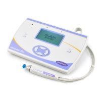
For connected parts marked * only connect the
accessories supplied with the instrument or supplied
by Amplivox or an Amplivox distributor. These parts
have been tested for use with the Model 270
Diagnostic Audiometer for compliance with the
standards IEC 60601-1 and IEC 60601-1-2. The use of
accessories other than those specified may
compromise compliance with these standards. For
other sockets refer to Appendix 4.

Related product manuals