10
2.3 OUTPUT TERMINALS AND WIRES
All models have terminal blocks on the rear panel which include positive and negative outputs, positive and
negative remote sense outputs, and earth ground.
<NOTE:>
The power supply is set at the factory for local sense operation (i.e. the +S and -S terminals are
strapped to the "+" and "-" terminals by a shorting plate at the rear terminal block). When
operating in remote sense mode, remove the shorting plate and refer to section 3.3 for remote
sense operation.
Additionally, all models have positive, negative and earth ground terminals in the front of the unit. Remote sense
capability is discussed in detail in section 3.3. A brief definition of remote sense is a measurement of voltage at the
load rather than at the output terminals.
Local connections are made to the "+" and "-" terminals of the power supply. Terminated loads only. Wrap and
bundle wires to reduce coupling effect.
In order to safely and sufficiently handle electric current, the proper wire size must be selected. Select a wire size
with sufficient rating to carry the current without overheating. Other factors to be taken into consideration are
voltage drop and conductor temperature.
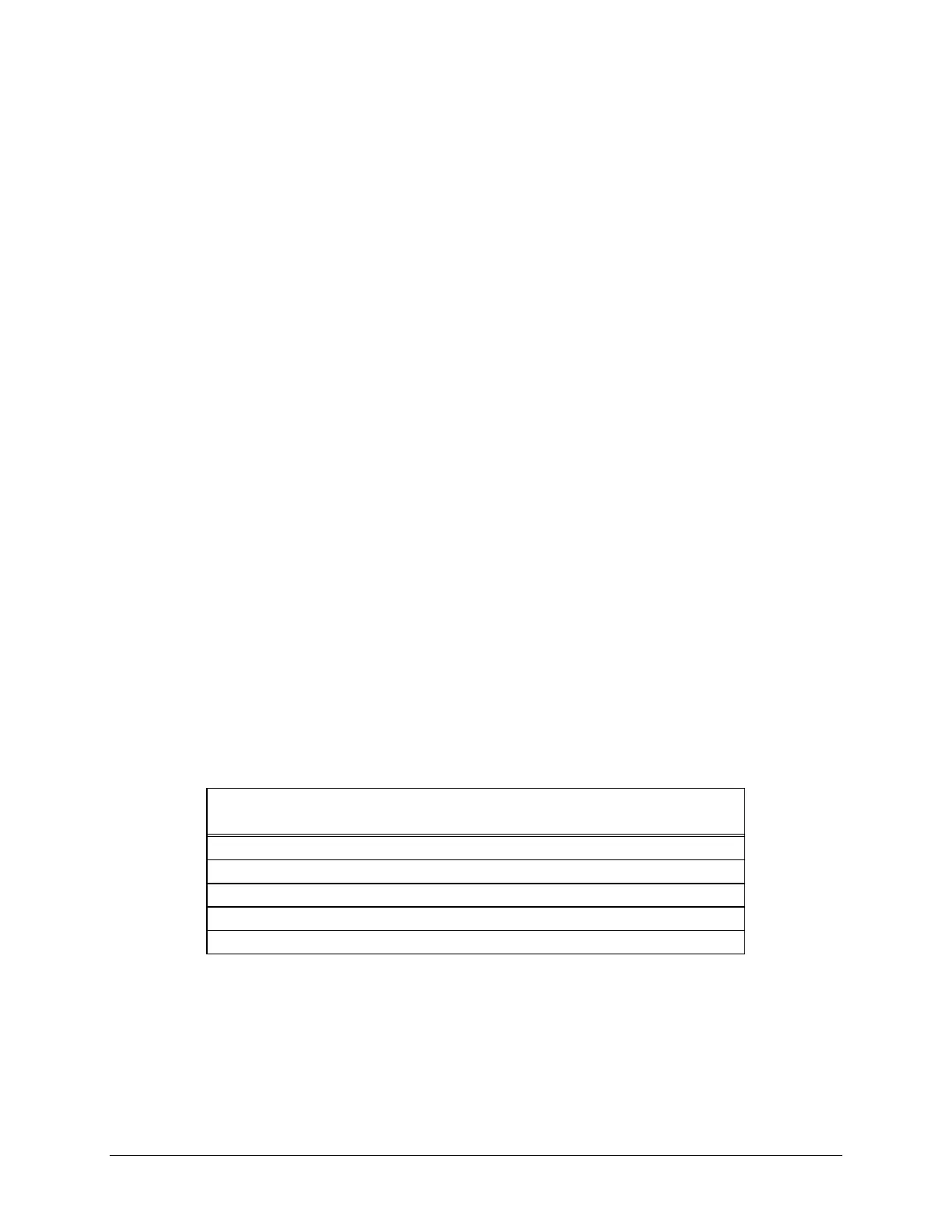
The following table lists current carrying capacity of various wire sizes. For further information please refer to the
NEC 1987 Handbook.
TABLE 1: Stranded Copper Wire Ampacity and Resistivity.
Ampacity Per Wire (Amps)
Wire Size 2 Wire Bundle 4 Wire Bundle Resistivity
(AWG) (Amps) (Amps) (ohm/ft)
20 7.8 6.9 0.0102
18 14.5 12.8 0.0064
16 18.2 16.1 0.0040
14 29.3 25.9 0.0025
12 37.6 33.2 0.0016