12
3.3 REMOTE SENSE
When the supply is locally strapped for local sensing (normal operation), an unavoidable voltage drop is incurred
in the load leads and this adds to its voltage regulation. By connecting the supply for voltage remote sensing, as
shown in figure G, voltage is sensed at the load rather than at the output terminals. This allows the supply to
automatically compensate for voltage drop in the load leads and improve regulation. In remote sensing, the
VOUT? query and the front panel meter monitor load voltage at the sensing points.
When the supply is connected for remote sensing, the OVP circuit senses at the main output terminal and not at the
sense points. The voltage sensed by the OVP circuit could be significantly higher than the voltage being regulated
at the load. Therefore, set OVP threshold voltage accordingly.
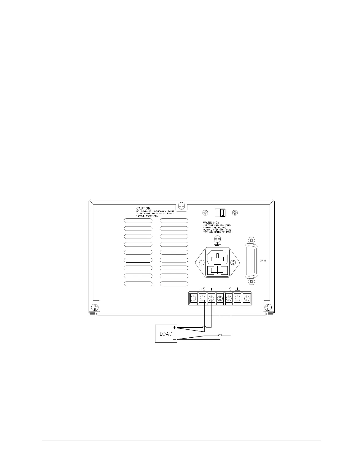
3.3.1 REMOTE SENSE CONFIGURATION
Turn off the power supply before modifying any connections on the rear panel terminal block. Configure the unit
for remote sensing by first disconnecting the shorting plugs between the sense and load terminals. Connect the load
and sense leads to the load as in figure G. Bear in mind that sense and load leads should be as short as possible.
Additionally, the sense leads resistance should be no greater than 0.5 ohm/lead, and the voltage drop over the load
leads should be no greater than 0.5V/lead.
Figure G. Remote Sense Configuration
3.3.2 REMOTE SENSE CHARACTERISTICS
OUTPUT NOISE: Any noise picked up on the sense leads will appear at the supply's output and may adversely
affect CV load regulation. Twist the sense leads to minimize external noise pickup and run them parallel and close
to the load leads. In noisy environments, it may be necessary to shield the sense leads. Ground the shield at the
power supply end only. Do not use the shield as one of the sensing conductors.