Do you have a question about the AMX FG5756 and is the answer not in the manual?
The AMX AXB-VOL3 (FG5756) is a 3-channel volume controller designed for audio systems, offering precise control over line-level audio signals. This device is engineered to provide flexible and reliable audio management, making it suitable for various professional audio environments.
The primary function of the AXB-VOL3 is to control the volume of up to three independent audio channels. Each channel handles line-level audio signals and can be configured for either balanced or unbalanced operation, providing versatility to integrate into different audio setups. A key feature is the opto-isolation of the audio ground from the system ground, which helps to minimize noise and interference, ensuring a cleaner audio signal.
The device offers granular control over audio levels with 128 distinct volume steps, allowing for very fine adjustments to the audio output. In addition to volume control, it supports audio mute functionality for each channel, enabling quick silencing of audio when needed. The AXB-VOL3 also incorporates variable ramp speed, which allows for smooth transitions between volume levels, preventing abrupt changes that can be jarring to listeners. Furthermore, it supports level presets, enabling users to quickly recall predefined volume settings for specific scenarios or preferences.
Communication and power for the AXB-VOL3 are handled via an AxLink connection. This 4-pin captive wire connector receives both power and control information from an AxLink Central Controller, simplifying wiring and integration into an AMX control system. The device's operation is managed through programming commands, which allow for comprehensive control over its functions, including setting ramp rates, recalling presets, and adjusting individual channel levels.
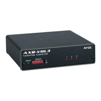
The AXB-VOL3 is designed for straightforward integration and operation within an AMX control system. Before use, the device's unique number must be set via an 8-position DIP switch located on the front panel. This device number must correspond to the assignment in the Axcess program, ensuring proper communication with the central controller. The device number is determined by the sum of the values of the switches in the ON position, and any changes require cycling the power to take effect.
Connecting the device involves preparing captive wires by stripping a quarter-inch of insulation, inserting them into the appropriate openings on the connectors, and tightening the screws. Care should be taken not to overtighten the screws to prevent damage. The AxLink connector handles both data and power, simplifying the wiring process. The device requires 12 VDC power, typically supplied by a PSN2.8 power supply or directly from the AxLink cable from the Central Controller. Guidelines are provided for maximum wiring distances based on wire gauge, ensuring reliable power delivery and communication.
For audio connections, the AXB-VOL3 features 6-pin captive wire connectors for each of its three volume channels. These connectors support both unbalanced and balanced line operation. For unbalanced operation, the IN- terminal is typically jumpered to GND. For balanced operation, both IN- and IN+ terminals are used. An optional 600-ohm resistor can be added for impedance matching if required by the audio system.
The front panel includes an AxLink LED, which provides visual feedback on the device's status. A green blinking LED indicates active AxLink communication and power. A full-off state signifies no power or a malfunctioning controller, while a full-on state indicates power is present but no AxLink control activity. Additionally, red channel LEDs (1-3) illuminate individually to indicate changes in channel levels, offering immediate visual confirmation of volume adjustments.
Programming the AXB-VOL3 involves using specific Axcess programming commands. These commands allow for detailed control over volume ramping, muting, and level presets. For example, the PLT command can ramp specified channels to a preset level or percentage over a defined time, enabling smooth volume transitions. The PR command sets the ramp rate for full-range volume changes, allowing users to customize the speed of volume adjustments. Another useful command allows for setting one channel's level to match another, simplifying synchronization of multiple audio paths. It's important to note that ramping a volume channel while its mute is active will not automatically disengage the mute; the volume change will only become audible once the mute is turned off.
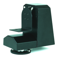
The AXB-VOL3 is designed for minimal maintenance, focusing on robust construction and reliable operation. The enclosure is made of metal with a black matte finish, providing durability and a professional appearance suitable for various installations. Its compact dimensions allow for flexible placement within equipment racks or other spaces.
The device's opto-isolated audio ground contributes to its long-term reliability by protecting against ground loops and electrical interference, which can degrade audio quality and potentially damage components over time. The use of captive wire connectors ensures secure and stable connections, reducing the likelihood of intermittent issues due to loose wiring.
While the device itself requires little active maintenance, ensuring proper power supply and adherence to wiring guidelines is crucial for its continued performance. Regular checks of the AxLink LED can help in quickly diagnosing communication or power issues, facilitating prompt troubleshooting. The device's design, with its focus on stable connections and robust internal components, aims to provide consistent and trouble-free audio control for extended periods.
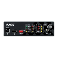
| Product Type | Controller |
|---|---|
| IR Ports | 2 |
| RS-232 Ports | 2 |
| I/O Ports | 8 |
| Ethernet Ports | 1 |