Installation
19
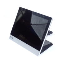
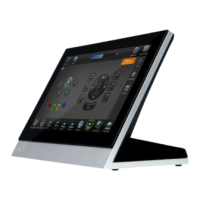
MXD/T-700 7" Modero X Series® Touch Panels
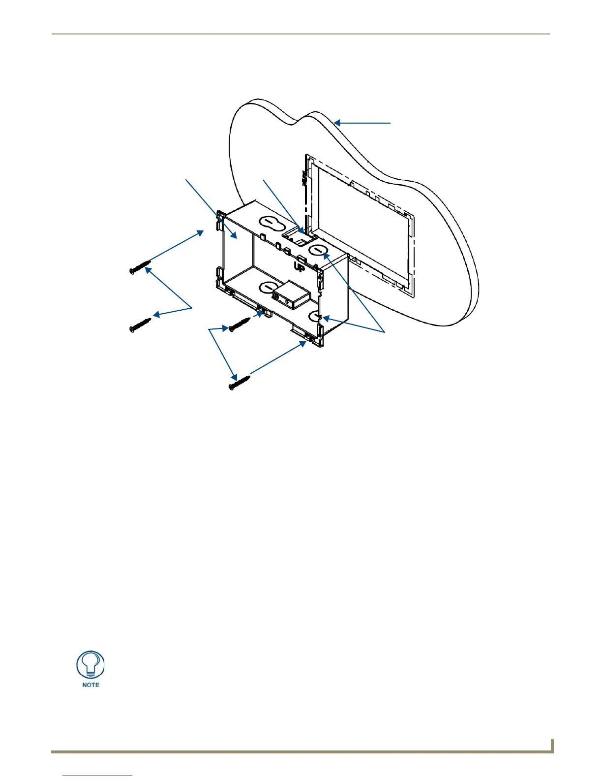
4. Thread the incoming Ethernet from their terminal locations through the surface opening (FIG. 19). Leave enough
slack in the wiring to accommodate any re-positioning of the panel.
5. Remove the back box knockouts (FIG. 19) and thread the incoming wiring through the knockout holes.To facilitate
installation, thread the Ethernet cable through a bottom knockout (Landscape) or a right-side knockout (Portrait),
and the USB cable through a top knockout (Landscape) or left knockout (Portrait)
6. Thread the incoming Ethernet and USB wiring (if USB access is desired) from the surface opening and through the
knockouts.
7. Push the back box into the mounting surface. Insure that the locking tabs lie flush against the back box and that the
back box goes freely into the opening.
8. Extend the locking tabs on the sides of the back box by tightening the screws inside the box until snug. Not all of
the tabs must be extended to lock the back box in place, but extending a minimum of the top and bottom tabs is
highly recommended. Apply enough pressure to the screw head to keep the box flush with the wall: this ensures that
the locking tabs will tighten up against the inside of the wall.
The back box is clear to allow visual confirmation that the tabs have been extended and are gripping the wall, as
well as in assisting with removal if necessary.
9. For additional strength, #4 mounting screws (not included) may be secured through circular holes located at the left
and right sides of the MXD-700 (FIG. 19). In order to prevent damage to the touch panel, make sure that these are
flush with the back box.
10. Insert each connector into its corresponding location along the back of the device (FIG. 15). To reach the RJ45
connector, gently pull it from beneath the electronics cover (FIG. 16). Attach the Ethernet cable and gently push the
connection back under the cover.
FIG. 19 MXD-700 Back Box Installation (Landscape)
Knockouts
Back Box
Mounting Surface
Locking
Tab
#4 Screws
To facilitate connection of the RJ45 connector to the Ethernet cable, press the RJ45’s
cable into the RJ45 cable clip to hold it in a stable position. Make sure to remove the
cable from the cable clip before continuing the rest of the installation.
 Loading...