Installing Wall-Mount (MXD) Panels
35
Modero S Series G4 Touch Panels Instruction Manual
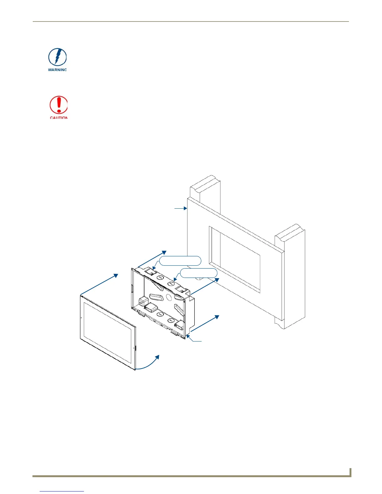
3. After ensuring proper placement, cut out the mounting surface for the Backbox, using the MSD-1001-L Installation
Template as a guide.
4. Thread the incoming Ethernet and Micro-USB wiring (if Micro-USB access is desired) from their terminal
locations through the surface opening (FIG. 21).
Leave enough slack in the wiring to accommodate any re-positioning of the panel.
5. Remove the Backbox knockouts and thread the incoming wiring through the knockout holes (FIG. 21). Note that
while FIG. 21 shows the MXD-1001-L, the illustration applies to all S Series panels. The only difference is the
dimensions and the number of knockouts and locking tabs.
6. Thread the incoming Ethernet and Micro-USB wiring (if USB or Micro-USB access is desired) from the surface
opening and through the knockouts.
7. Push the Backbox into the mounting surface.
Ensure that the locking tabs lie flush against the Backbox and that the Backbox goes freely into the opening.
8. Extend the locking tabs on the sides of the Backbox by tightening the screws inside the box until snug.
Using the included template to select the final placement of the Backbox is highly
recommended. The outside edges of the template are the same dimensions as the
touch panel, which allows you to troubleshoot possible conflicts with wall edges,
doors, and other potential obstacles.
Making sure the actual cutout opening is slightly smaller than the provided
dimensions is highly recommended. This provides a margin for error if the opening
needs to be expanded. Too little wall material removed is always better than too
much.
FIG. 21 MSD-1001-L Backbox Installation
Backbox
MSD-1001-L
4X Locking tabs
4X Knockouts
Mounting Surface