EVAL-ADAU1701MINIZ
Rev. 0 | Page 4 of 12
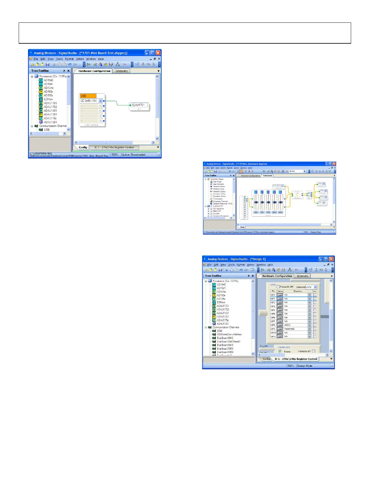
08060-031
Figure 3. Hardware Configuration Tab
To complete the following steps, you will be working with the
Schematic tab.
1. Click on the Schematic tab.
2. In the Tree Toolbox, expand the IO folder, then select
Input. Click and drag an Input cell to the work area.
3. In the IO folder, select GPIO, then select Input. Click and
drag an Auxiliary ADC Input to the work area.
4. On the Auxiliary ADC Input cell, labeled ADC In1, select
AUX_ADC_3 from the pull-down menu.
5. Expand Filters, select Second Order, then select Single
Precision, then select 2 Ch, and click and drag Medium
Size Eq.
6. Right-click the General (2
nd
Order) cell labeled Gen
Filter1, click Grow Algorithm, then select 1. 2 Channel–
Single Precision, and then select 4. This creates a five band
EQ. Each band’s general filter settings can be modified by
clicking the blue boxes on the cell.
7. Expand Volume C ontro ls , then select the following:
Adjustable Gain, then Ext Control, then Clickless SW
Slew, and then click and drag Single slew ext vol.
8. Expand Muxes/Demuxes and then select Switch, then
select 2 Ch and then click and drag Stereo Switch 2xN.
9. Expand IO and select Output. Click and drag four Output
cells to the work area.
10. For each of the outputs select a DAC output from the pull-
down menu. DAC0 and DAC1 are amplifier left and right
outputs (J4 on the board marked in Figure 2, respectively).
DAC2 and DAC3 are left and right channel outputs,
respectively, for the stereo lineout output (J6 on is shown
in Figure 2).
11. C
onnect all the cells as depicted in Figure 4.
To complete the steps, you will be working with the Hardware
Configuration tab.
1. In the Hardware Configuration tab under the GPIO box
(see Figure 5), select the pull-down menu next to MP8 and
set for ADC3. This allows the rotary potentiometer on the
board to be used as a volume control in conjunction with
the Auxiliary ADC Input cell in the schematic window
(see Figure 5).
2. Make sure your project board is powered and connected to
the PC.
3. Select the Link-Compile-Download button in
SigmaStudio. If the project compiled without error, you
will be in Ready-Download mode.
Your screen should now appears as shown in Figure 4.
08060-032
Figure 4. Schematic Tab, Full Design
08060-033
Figure 5. Hardware Configuration, GPIO Setting
Once you start the audio source and hear the audio playing, you
can rotate the potentiometer on the board to control the volume
in real time and affect the audio output.

 Loading...


