14
Step 2: Assembling Arches
2.1 Pre-assembly of arch components: Identify and layout all components according to Figure 2.1 for the entire
structure. NOTE: Setting uprights and rafters on 4 x 4 wood blocking (or whatever blocking may be available) will make
the insertion of the pins and bolts easier.
2.1.1 The following is a list of components required for each arch:
Quantity Description
2
Base Plate L-Pins 16mm x 230mm (9”) & R-Clips NOTE: 5/8” x 200mm (7 7/8”) L-Pins are used at
the Gable End base plates (Quantity is one per upright)
2 Uprights
2 Base Plates
2 Rafter/Upright Pin with Flat 14mm x 140mm (5 1/2”)
4 (8)
16mm x 132mm (5 3/16”) Locking L-Pin with stop. (quantity in parenthesis is required if Rafter
Extensions are used) NOTE: Also used at Gable End uprights.
1 Ridge Insert
2 Rafter Extensions (if applicable)
2.1.2 Identify and layout Pins with R-Clip (as required) as shown in Figure 2.1.
2.1.6 If laying out components for a cable braced bay, refer to Section 2.3 for substitute components required.
2.2 Assembly of Uprights and Rafters (and Rafter Extensions if applicable): The assembly of the arches
is easier if working from one side to the opposite side.
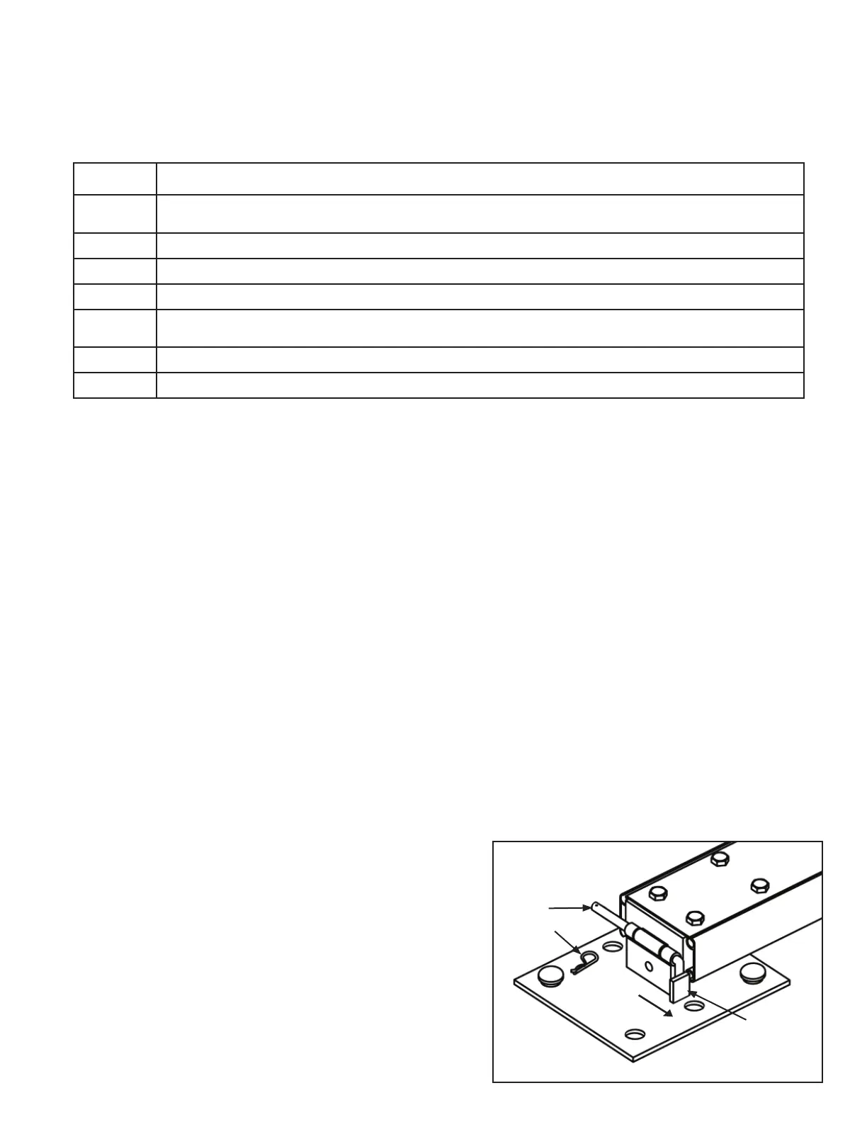
2.2.1 Starting at Base Plate “1”, connect the bottom of the Upright Connection Insert to the Base Plate using the L-Pin as
shown in Figure 2.2. The R-Clip will be inserted later when the Wall Ground Bars are installed. IMPORTANT:
The short leg of the L-Pin must be turned down and behind the Safety Tab on the Base Plate to keep the L-Pin
from sliding out.
2.2.2 Connect Rafter to the Upright Assembly by sliding the Rafter onto the slide connector on top of the upright. Secure
the connection by inserting the Flat L-pin into the hole located inside the end of the rafter, see Figure 2.2a.
2.2.3 If installing Rafter Extensions, connect the Rafter Extension to the Rafter using Locking L-Pins. Ensure L-Pin is
turned so the stop collar is locked behind tab on rafter. IMPORTANT: At the gable ends, the head of the pin must
be on the exterior side of the rafter to minimize any snagging possibilities when installing the gable end fabric.
2.2.4 Insert Ridge Weldment into end of rafter and secure using Locking L-Pins. Ensure L-Pin is turned so the stop collar
is locked behind tab on rafter. See Figure 2.2b. IMPORTANT: At the gable ends, the head of the pin must
be on the exterior side of the rafter to minimize any snagging possibilities when installing the gable end fabric.
2.2.5 Complete the Arch assembly by connecting the opposite Rafter (or Rafter Extension) to the Ridge Weldment,
Rafter Extension to Rafter (if applicable), Rafter to Upright
and Upright to Base Plate according to steps 2.2.1 thru
2.2.4.
2.2.6 Assemble the remaining arches according to steps 2.2.1
thru 2.2.5.
2.2.7 When Ridge and Knee Braces are required as shown in the
configuration drawing, insall as shown in Figures 2.2a &
2.2b.
R-Clip
Figure 2.2
L-Pin
Safety Tab
To inside of tent
 Loading...