5) FRONT HOPPER MOTOR ERROR [E.61], FRONT HOPPER SENSOR ERROR [E.61]
▶SOLUTION : FRONT HOPPER MOTOR ERROR [E.61]
※ 1 HOW TO TEST : TEST MODE → FRONT HOPPER TEST→ SELECT button →SHOOTING button
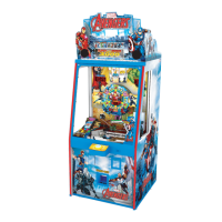
2 Check the jamming location Token Bridge, Pusher Plate and Conveyor ( P1 )
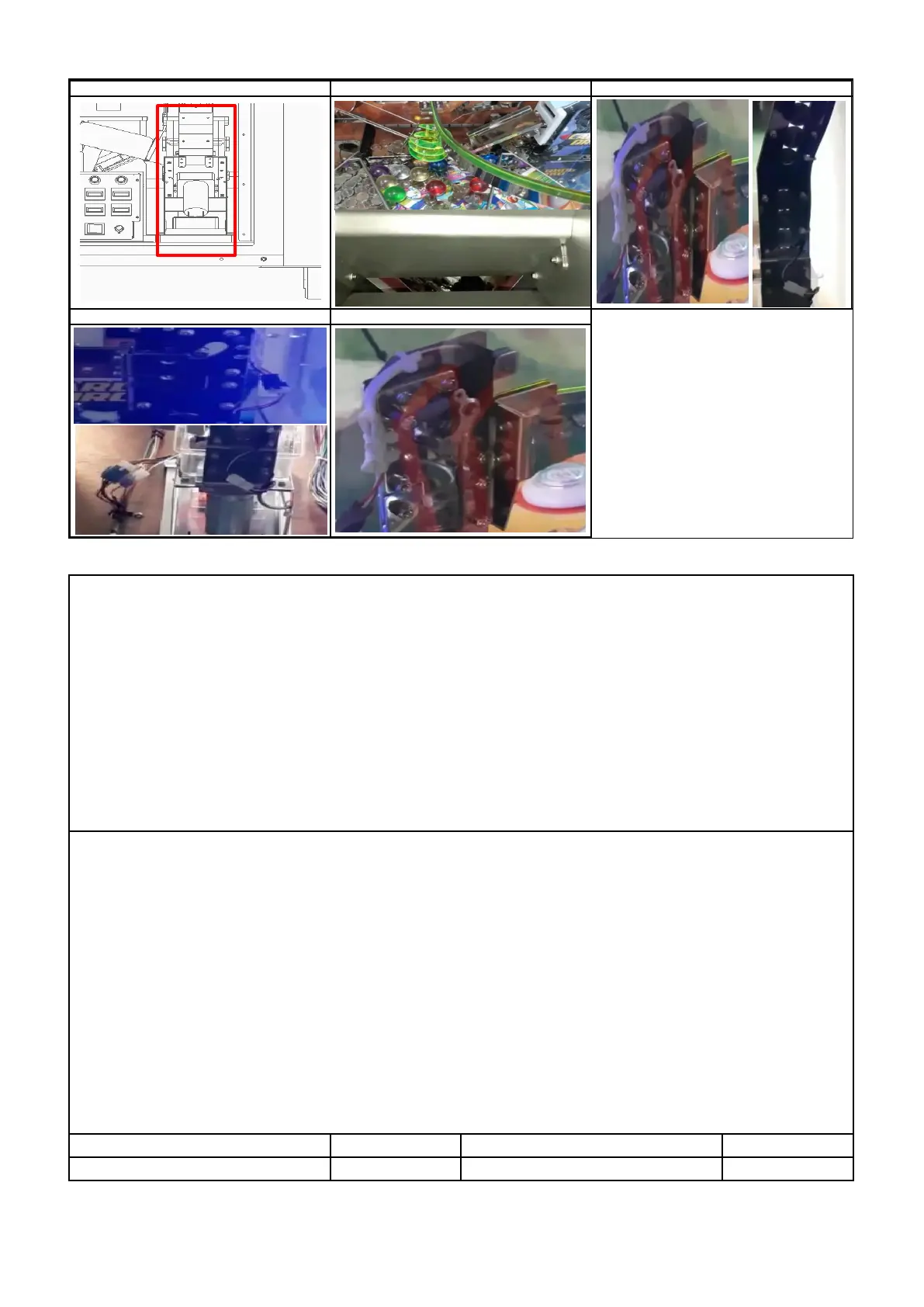
3 Foreign objects inside the HOPPER,Check jamming hopper disk,Check jamming hopper rail (P2 )
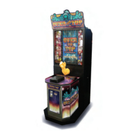
4 Check the disk rotation direction, Check connection of motor connector (P3 )
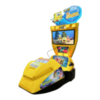
5 Check the operation of HOPPER PCB internal LED1 (lights up during operation),
LED2 (flashes when 5V input), LED3 (flashes when 24V is input) (P4 )
6 Check the dc voltage ( HOPPER PCB / JP2 ) : PIN 1 : Over 23V , PIN 2 : GND
7 Replace HOPPER PCB
8 Check the dc voltage ( MAIN PCB / CN10 ): A-PIN 1 : Over 23V , A-PIN 6 : Over 4.5V , A-PIN 10 : GND
9 Replace MAIN PCB
▶SOLUTION :FRONT HOPPER SENSOR ERROR [E.61]
1 HOW TO TEST : TEST MODE → FRONT HOPPER TEST→ SELECT button →SHOOTING button
※
1 Check the jamming location Token Bridge, Pusher Plate and Conveyor ( P1 )
2 Check the jamming launch part exit (P2 )
3 Check the jamming hopper rail ( P2 )
4 Check connection of sensor connector ( P3 )
5 Check the foreign substances in the sensor part and the assembly status of the launch part (P4)
6
: PIN 1 : over 4.5V , PIN 3 : below 0.5V , PIN 4 : GND ,