APPENDICES
85
SERVICE PROCEDURE D24-III
Main Burner Operation Testing
CAUTION
Be Careful When Making Voltage
Measurements or Jumping Terminals
Not to Damage or Deform Connectors or
Connector Pins.
DANGER
120 volt exposure. To avoid personal injury,
use caution while performin g this procedure.
Condition:
Main burner short cycles.
Control Display may show error
code “63, 57, or 4” and be in
“Soft Lockout” stat e.
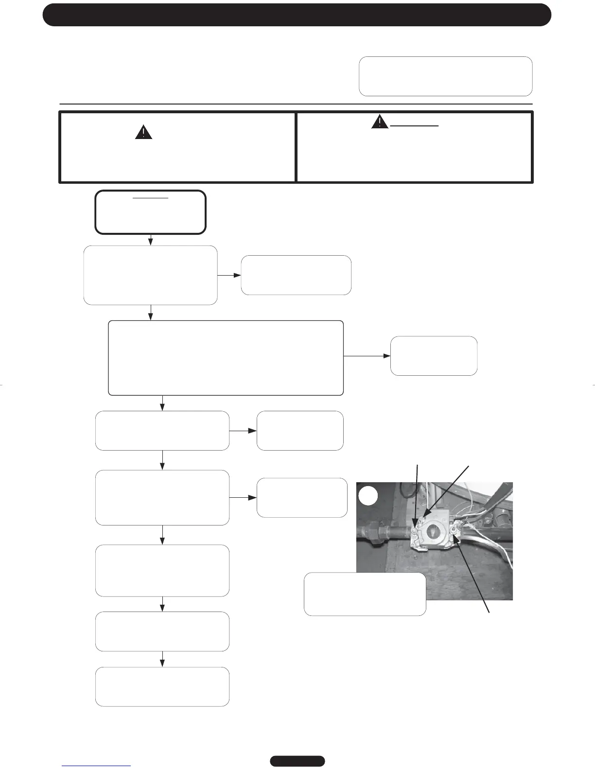
Check gas inlet pressure to the water
heater gas valve.
Line pressure should be:
Nat. = Min. 5.5" W.C.: Max. 14.0" W.C.
LP = Min. 11.0" W.C.; Max. 14.0" W.C.
Is gas pressure within proper
specification? (see photo below)
Determine cause of incorrect gas
pressure and correct. Contact
your gas supplier.
Check venting conditions, clogged vent,
down drafts or negative building
pressure
Is vent system okay?
Correct improper venting
condition. Refer to
Installation Instructions
N
Is there sufficient combustion air being
supplied to the water heater? Are there
combustion air openings or supply pipes
to the room? Open access door to the
utility room to see if problem is
corrected.
Provide proper
combustion air to water
heater. Refer to
Installation Instructions
N
Check burner tubes for scale or debris
build-up. Clean burner as necessary.
(see Main Burner and Pilot Removal and
Inspection)
Checktankfluesforblockageordebris
build-up causing restriction.
(see Flue Baffle Removal, Inspection)
Check for unstable pilot flame or
oxidation of the flame rod on pilot
causing weak pilot signal. Make sure
pilot shield is in place and does not
touch pilot flame sensor.
(See Pilot Inspection section)
Line gas
pressure port
Manifold Pressure Port with hose
barb inserted for measuring
pressure
N
Y
Y
Page 31
Check manifold pressure. See photo on lower right section of page f or
manif old pressure ta p location. Ref er to water h eat er rating label for
specified manifold pressure. If the manifold pressure is not within 0.3"
w.c. of t he specified pressur e, then remove the regulator cap fr om t he
gas valv e and t urn plastic screw c lock w ise t o inc r eas e pr es sur e and
counterclockwise to decrease pressure. Be sure inlet gas pressure is at
least 1" w.c. above the manifold pressure. Replace regulator screw and
pressure tap cap when finished. Is manifold pressure O.K.?
Gas Valve pressure
regulator cap (adjustment
screw accessible by
removing cap screw)
16
Replace Gas Valve.
N
Y
Y
Connect hose barb to manifold
pressure port shown above, then
connect monometer to measure
gas manifold pressure.