Do you have a question about the andrews MAXXflo EVO CWH 90/302 and is the answer not in the manual?
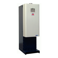
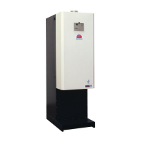
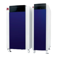
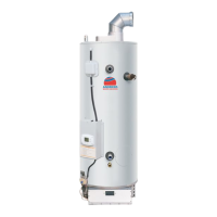
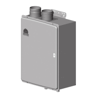
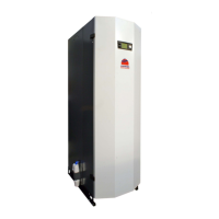
Details the MAXXflo EVO as a gas-fired, low NOx, twin heat engine water heater.
States the manual is for heating specialists installing commercial/industrial plant.
Covers essential safety advice, including gas leaks, handling, and general precautions.
Lists relevant standards, codes of practice, and building regulations for installation.
Details the data plate information and compliance with directives/regulations.
Provides key technical specifications like electricity and fuel consumption, noise levels.
Presents energy efficiency class, annual consumption, and thermostat settings.
Details heat input, output, gas consumption, flue data, and electrical specifications.
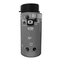
Provides physical dimensions, connection types, and port details for the heater.
Shows schematic diagrams for single and parallel MAXXflo EVO installations.
Illustrates wiring and related settings for circulation pumps and sensors.
Depicts a schematic for MAXXflo EVO with a buffer tank.
Shows wiring and settings for MAXXflo EVO with a storage tank and expansion module.
Illustrates BMS (Building Management System) connections for the heater.
Provides detailed wiring diagrams for the main control board (PCB1).
Shows wiring diagrams for the second control board (PCB2).
Guides on selecting a suitable location for the heater, considering flue, air, and access.
Step-by-step instructions for removing the heater's outer door and inner cover, including bracket removal.
Details connections, system type, water quality, and anti-vacuum valve requirements.
Explains requirements for unvented systems, including the use of specific kits and components.
Details how to fit a secondary return circuit and maximum flow rates.
Guides on condensate discharge pipework, material requirements, and trap filling.
Covers general requirements, suitable flue materials, and standards for flue systems.
Specifies ventilation requirements for type B23 flue appliances in rooms and enclosures.
Details minimum vent free areas for enclosures ventilated directly to outside air.
Provides minimum distance requirements for flue terminal positions based on location codes.
Explains room sealed flue arrangements, terminal positions, and ventilation requirements.
Lists part numbers and descriptions for flue kits and optional flue parts.
Illustrates horizontal, vertical, and alternative flue setup configurations.
Provides dimensions for various concentric flue components like terminals, traps, and elbows.
Details minimum distance requirements for concentric/twin flue terminal positions.
Explains Flue Equivalent Length (FEL) and provides tables for calculating total FEL.
Covers gas supply requirements, meter types, and pressure specifications.
Guides on electrical connections, volt-free functions, and communication protocols.
Provides a step-by-step guide for filling the DHW tank and system with water and removing air.
Details commissioning the heat engines, including important notes, top engine process, and bottom engine process.
Details final steps for heat engine commissioning, including refitting connectors and checking gas consumption.
Explains the procedure for converting the heater from natural gas to LPG.
Covers frost protection, Legionella risks, and anti-legionella settings and controls.
Covers setting time/date, checking sensor position, cleaning, and user handover procedures.
Details operation sequences, faults, lockouts, and fault display examples.
Recommends regular servicing intervals and lists minimum annual servicing requirements.
Details steps to remove the heat exchanger, fan, and venturi for burner inspection and cleaning.
Recommends replacing electrodes every two years and provides inspection guidance.
Advises on checking flue sections for firm connection and inspecting seals for leaks.
Guides on inspecting condensate pipework for leaks and cleaning the syphon trap.
Details how to check and adjust gas rate and combustion by analyzing flue gas.
Provides procedures for inspecting, cleaning, and flushing the DHW storage tank.
Details procedures for removing and changing various heater components.
Explains the location and procedure for removing and replacing the flue temperature sensor.
Details the location and procedure for removing and replacing the common flow temperature sensor.
Guides on removing and replacing the AVS37 GUI display unit.
Provides instructions for replacing the Master and Slave control PCBs, emphasizing ESD precautions.
Details how to remove and replace the spark generator, including power connections.
Guides on removing and replacing the combustion fan, including venturi and gasket checks.
Provides instructions for removing and replacing the gas valve, including transfer of gasket and orifice.
Details how to remove spark and ionisation electrodes, ensuring gasket seal integrity.
Guides on inspecting and replacing the Back Flow Prevention Valve (BFPV) and air arm seal.
Details how to locate and replace the overheat thermostat.
Guides on removing and replacing the air pressure switch, including air tube and connections.
Provides instructions for removing the heat exchanger, including draining water and disconnecting sensors.
Details steps for removing and replacing the circulation pump Q1, including refilling and bleeding.
Guides on removing and replacing the water pressure sensor, including connector and clip removal.
Provides instructions for flushing and descaling heat exchangers, applicable when sensors/pipework are fitted.
Illustrates and lists part numbers for various components.
Lists essential first aid kit contents for maintaining heat engines in operation.
Lists error codes, descriptions, diagnostic codes, and notes for troubleshooting.
Lists error codes, descriptions, diagnostic codes, and notes for troubleshooting.
Lists error codes, descriptions, diagnostic codes, and notes for troubleshooting.
Lists error codes, descriptions, diagnostic codes, and notes for troubleshooting.
Provides sensor resistance values for NTC 10K and 20K sensors.
| Category | Water Heater |
|---|---|
| Model | MAXXflo EVO CWH 90/302 |
| Gas Type | Natural Gas |
| Max. Gross Heat Input (kW) | 90 |
| ErP Water Heating Efficiency Class | A |
| Nox Class | 5 |
| Voltage | 230 |
| Type | Condensing |
| Water Tank Capacity (L) | N/A (Continuous Flow) |
| Phase | Single Phase |
| Protection Rating | IPX5 |